You are here: Foswiki>Timing Web>TimingSystemDocumentation>TimingSystemDocuments>TimingSystem50HzSync (20 Nov 2024, DietrichBeck)Edit Attach
WR-F50: Synchronizing the White Rabbit Data Master to 50 Hz Mains
Introduction
Stability of Linac-RF systems are vital for a stable operation of UNILAC. As many RF amplifier tubes are directly heated using AC mains, UNILAC must be operated synchronously to the 50 Hz mains power with a cycle time of 20 ms. As low jitter and phase-noise are a key feature of the White Rabbit based timing system, the White Rabbit grandmaster uses a GPSDO as reference clock. Moreover, White Rabbit and the BuTiS clock distribution system of the Ring -RF must be hard-locked to each other. Thus, White Rabbit and 50 Hz mains are not synchronized to each other. As a solution, the injector Data Master must be configured such, that it plays UNILAC cycles synchronously to the 50 Hz mains. The synchronization of the injector Data Master to 50 Hz mains is implemented by a dedicated synchronization unit,wr-f50.
The how-to for wr-f50 is included in the how-to of the White Rabbit to MIL gateways click.
Setup
Principle
 Figure: Principle of synchronisation. Top: trigger signal of 50 Hz mains rising edge. Bottom: Cycle start of UNILAC.
The idea behind the synchronization is to tune the cycle length of UNILAC, played by the injector Data Master. This value must be known to the Data Master before the start of the next cycle. If the cycle length is not tuned, the Data Master will continue with the actual value. The situation is shown in the figure above. This is the situation:
 - the start of cycles #1..5 are not synchronized to 50 Hz mains.
- at time 'now' cycle #5 has already started and the length of cycle #5 is known to the Data Master
- hence, the beginning of cycle #6 is already fixed
- synchronization can with the start of cycle #7
- wr-f50 has registered previous 50 Hz triggers #1..5 and has to predict the 50 Hz trigger for cycle #7
- wr-f50 has has registered when the UNILAC cycle #5 has started
- wr-f50 knows the actual value of the UNILAC cycle length either
- from the start of cycles #4 and #5, or
- it 'knows' the value that it has been set previously, or
- uses the actual value, which is known from a timing message sent by the Data Master at the beginning cycle #5
- (we have lots of possibilities for cross-checks and diagnostics here)
- wr-f50 can calculate the length of cycle #6 that is required for synchronization at the start of cycle #7
Procedure
The communication between Data Master an wr-f50 is implemented by sending timing messages via the White Rabbit network using the following group ID and event numbers.- GID
PZU_F50; TOS internal information related to UNILAC 50 Hz synchronization - EvtNo
CMD_UNI_F50DM; start of UNILAC 50Hz cycle (sent by Data Master) - EvtNo
CMD_UNI_F50TUNE; Tune Data Master 50 Hz cycle length (sent by WR-F50 SCU, 1000us after 50 Hz mains trigger signal)
- analyze the TTL signals from the 50 Hz trigger unit
- predict the deadline of the next but one 50 Hz trigger (at cycle start #7)
- analyze the actual length of UNILAC cycles (
CMD_UNI_F50DM) - calculate the required length of cycle #6; the following limits are respected
- the length of a cycle must never be shorter than 19800 us
- the length of a cycle must never exceed 24000 us
- send the predicted length to the Data Master as timing message
CMD_UNI_F50TUNEvia the White Rabbit network - the Data Master receives the timing message at the input of its ECA and the value is written to a dedicated register (only known to the Data Master itself)
Prediction
At present we use the assumption that the 'deadlines' of the 50 Hz trigger signal follow a linear function. The parameters of the function are determined by linear regression of the past N deadlines. The prediction is then done by using the linear function. See below for more information.Example
[ruth@scuxl4711 ~]# saft-ctl tr0 -vx snoop 0x14c0000000000000 0xffff000000000000 0
...
tDeadline: 2024-11-19 15:56:48.652213272 FID: 0x1 GID: 0x04c0 EVTNO: 0x0a01 Param: 0x0000000000000000 // rising edge mains trigger; offset to start is 0.741 us
tDeadline: 2024-11-19 15:56:48.652214013 FID: 0x1 GID: 0x04c0 EVTNO: 0x0fc0 Param: 0x0000000001313e95 // start of UNILAC cycle
tDeadline: 2024-11-19 15:56:48.653213272 FID: 0x1 GID: 0x04c0 EVTNO: 0x0fc1 Param: 0x0000000001313dbd // tune word; set-value is 20004.285 us (*)
tDeadline: 2024-11-19 15:56:48.672216752 FID: 0x1 GID: 0x04c0 EVTNO: 0x0a01 Param: 0x0000000000000000 // rising edge mains trigger; offset to start is 1.762 us
tDeadline: 2024-11-19 15:56:48.672218514 FID: 0x1 GID: 0x04c0 EVTNO: 0x0fc0 Param: 0x0000000001313dbd // start of UNILAC cycle;
tDeadline: 2024-11-19 15:56:48.673216752 FID: 0x1 GID: 0x04c0 EVTNO: 0x0fc1 Param: 0x0000000001313dca // tune word; set-value is 20004.298 us (**)
tDeadline: 2024-11-19 15:56:48.692221232 FID: 0x1 GID: 0x04c0 EVTNO: 0x0a01 Param: 0x0000000000000000 // rising edge mains trigger; offset to start is 1.567 us
tDeadline: 2024-11-19 15:56:48.692222799 FID: 0x1 GID: 0x04c0 EVTNO: 0x0fc0 Param: 0x0000000001313dca // start of UNILAC cycle; cycle length was 20004.285 us (*)
tDeadline: 2024-11-19 15:56:48.693221232 FID: 0x1 GID: 0x04c0 EVTNO: 0x0fc1 Param: 0x0000000001313d45 // tune word; set-value is 20004.165 us
tDeadline: 2024-11-19 15:56:48.712224712 FID: 0x1 GID: 0x04c0 EVTNO: 0x0a01 Param: 0x0000000000000000 // rising edge mains trigger; offset to start is +2.386 us
tDeadline: 2024-11-19 15:56:48.712227097 FID: 0x1 GID: 0x04c0 EVTNO: 0x0fc0 Param: 0x0000000001313d45 // start of UNILAC cycle; cycle length was 20004.298 us (**)
...
Figure: 'Snooping' on the wr-f50 SCU. EvtNo 0x0fc0: CMD_UNI_F50DM, signals start of UNILAC cycle, sent by Data Master. EvtNo 0x0fc1: CMD_UNI_F50TUNE, carries tune word, sent by wr-f50. EvtNo 0x0a01: rising edge of 50 Hz signal (internal event from ECA TLU). Marked by ('*', '**'): set-value and corresponding cycle length. Details see text. The 'figure' above shows the output when 'snooping' on the wr-f50 SCU. The rising edge of the mains trigger and cycle start are always close to each other. The tune word (=cycle length) for the next cycle is coded into the low bits of the parameter field; this message (CMD_UNI_F50TUNE) is sent with a deadline exactly 1.000000 ms following the 50 Hz mains trigger. The start of an UNILAC cycle is signaled via a message from the Data Master (CMD_UNI_F50DM); this message has the cycle length coded into the parameter field and should match the previous set-value. Two messages marked by '*' show the set-value and the end of the corresponding cycle. Same for the two messages marked by '**'.
Firmware
 Figure: Synchronization of the Data Master to the 50 Hz mains frequency. The central components are the Data Master and the lm32 softcore (3d-boxes). Gray boxes: components of the SCU. White Boxes: Components outside the SCU. Numbers indicate data flow for certain activities; 1a: receive timing message from the Data Master; 1b: receive timestamp of 50 Hz trigger signal; 2: send 'tune word' to Data Master; 2': send 'tune word' to ECA for optional monitoring at the host.
The figure above depicts the synchronization process. Please note, that activities 1a and 1b have no predefined order.
1a: Start of UNILAC Cycle
At the beginning of each UNILAC cycle the Data Master send a timing message with EvtNo CMD_UNI_F50DM via the White Rabbit network. The lm32 firmware receives that message via the ECA. As payload, this timing message contains the length of the cycle in the low 32bits of the parameter field. Implicitly, this messages also announces the start of the next UNILAC cycle: the deadline of the next cycle is the sum of the cycle length to the current cycle and the deadline of this timing message.
1b: Start of a 50 Hz Mains Period
The 50 Hz mains is conditioned via the transformer FX202.031 and the trigger unit FX202.021 generates a TTL signal at the positive zero-transition of the 50 Hz mains signal. Via a Lemo cable, the TTL signal is connected to one of the inputs at the SCU, where timestamping is done in the Timestamp Latch Unit (TLU). This generates an event at the input of the ECA which is received by the lm32 firmware.
2: Data Master Control
The lm32 firmware uses a fixed number of the past N timestamps by the TLU to predict the deadline of the next but one 50 Hz trigger. As the start of the next UNILAC cycle is known (see 1a above), the length of the next cycle can be calculated to achieve a match of the next but one trigger and UNILAC cycle start. The firmware broadcasts a timing message with EvtNo CMD_UNI_F50TUNE to the White Rabbit network. This message contains the length of the next UNILAC cycle as payload. This message is received and processes by the Data Master.
Analysis
The lm32 firmware analyzes a couple of values for monitoring purposes
 - Offset between predicted and actual deadline of 50 Hz trigger; this allows to monitor the quality of the prediction and to detect unexpected changes in the 50 Hz mains power.
- Offset between deadlines of 50 Hz trigger and UNILAC cycle start; this allows to monitor how well the Data Master follows the 50 Hz mains signal.
- Offset between current and past deadlines of UNILAC cycle start; this allows to 'measure' the UNILAC cycle length. This value shall be identical to the set-value sent to the Data Master. If not, this is serious malfunction that may occur for two reasons.
- The Data Master has not received the set-value. This is easily checked, as the CMD_UNI_F50DM message from the Data Master carries the set-value (length of the UNILAC cycle) as payload.
- The Data Master has the correct set-value but the UNILAC cycle does not match the set-value. This is a malfunction of the Data Master.
- Length of UNILAC cycle. This value must respect the limits (min: 19800 us, max: 20400 us);
- Change of length of UNILAC cycle.
- 1a: start of UNILAC cycle via timing message with EvtNo CMD_UNI_F50DM
- 1b: 50 Hz mains trigger via timing message from TLU
- 2': new set-value of UNILAC cycle length via timing message with EvtNo CMD_UNI_F50TUNE
- CMD_UNI_F50DM: cycle start sent by Data Master
- CMD_UNI_F50TUNE: tune message sent by wr-f50
- 50 Hz mains trigger: deadline of CMD_UNI_F50Tune - 1000000 ns.
Raw Data
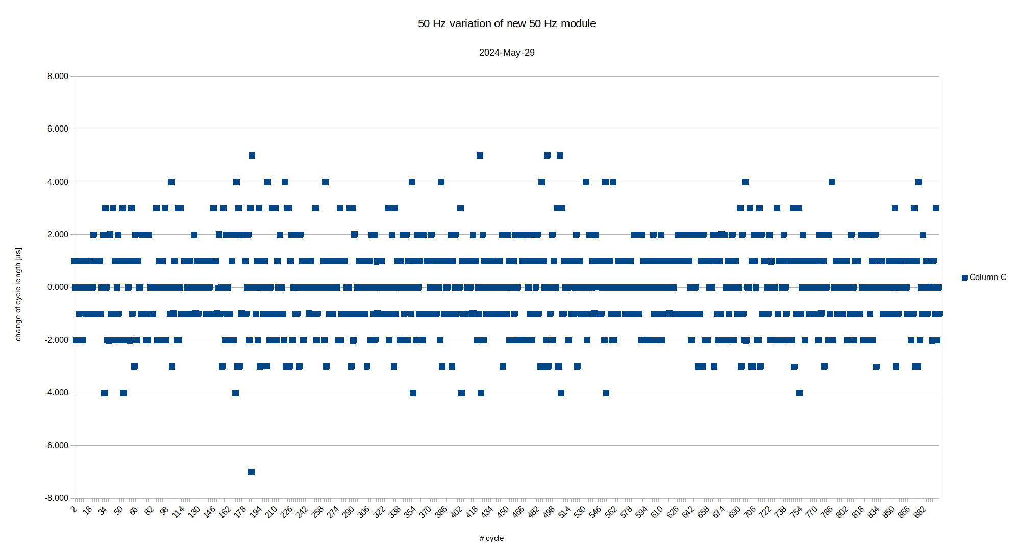
 Figure: Variation of 50 Hz mains period as a function of time / cycle number.
The figure above shows the variation of the 50 Hz period as a function of time. The granularity of the trigger signal is 1us. The typical variation of the cycle length is in the low one-digit microseconds range.
Performance
Smooth Operation
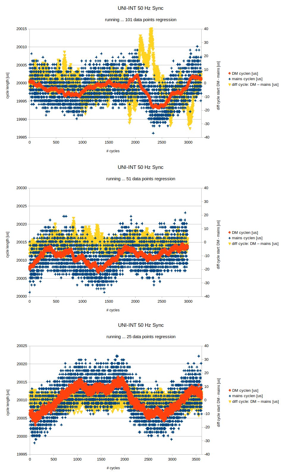
A small variation of the UNILAC cycle length means less work load for the RF-control loops. A small deviation of the UNILAC cycle start from 50 Hz mains means less stress for the RF amplifiers. Thus, one needs to find a compromise between a small variation and small deviation. Figure: Left y-axis: Cycle length of 50 mains (blue) and Data Master (red) as a function of cycle number. Right y-axis: Difference of cycle length between Data Master and mains. The graphs shows the behavior for different numbers of data points for the linear regression; 101 (top), 51 (middle) and 25 (bottom).
The figure above shows the performance of the synchronization depending on the number of data points used for the linear regression. Each data point is one deadline of the 50 Hz mains trigger. The higher the number of data points, the smaller will the variation of the UNILAC cycle length but the larger will be the difference to the 50 Hz mains.
The figure with 25 data points for the linear regression was preferred by the colleagues from linac-RF. A dry-run followed by a wet-run from 21 October to 8 November 2024 yielded no issues for the linac RF-system.
50 Hz Mains Jumps
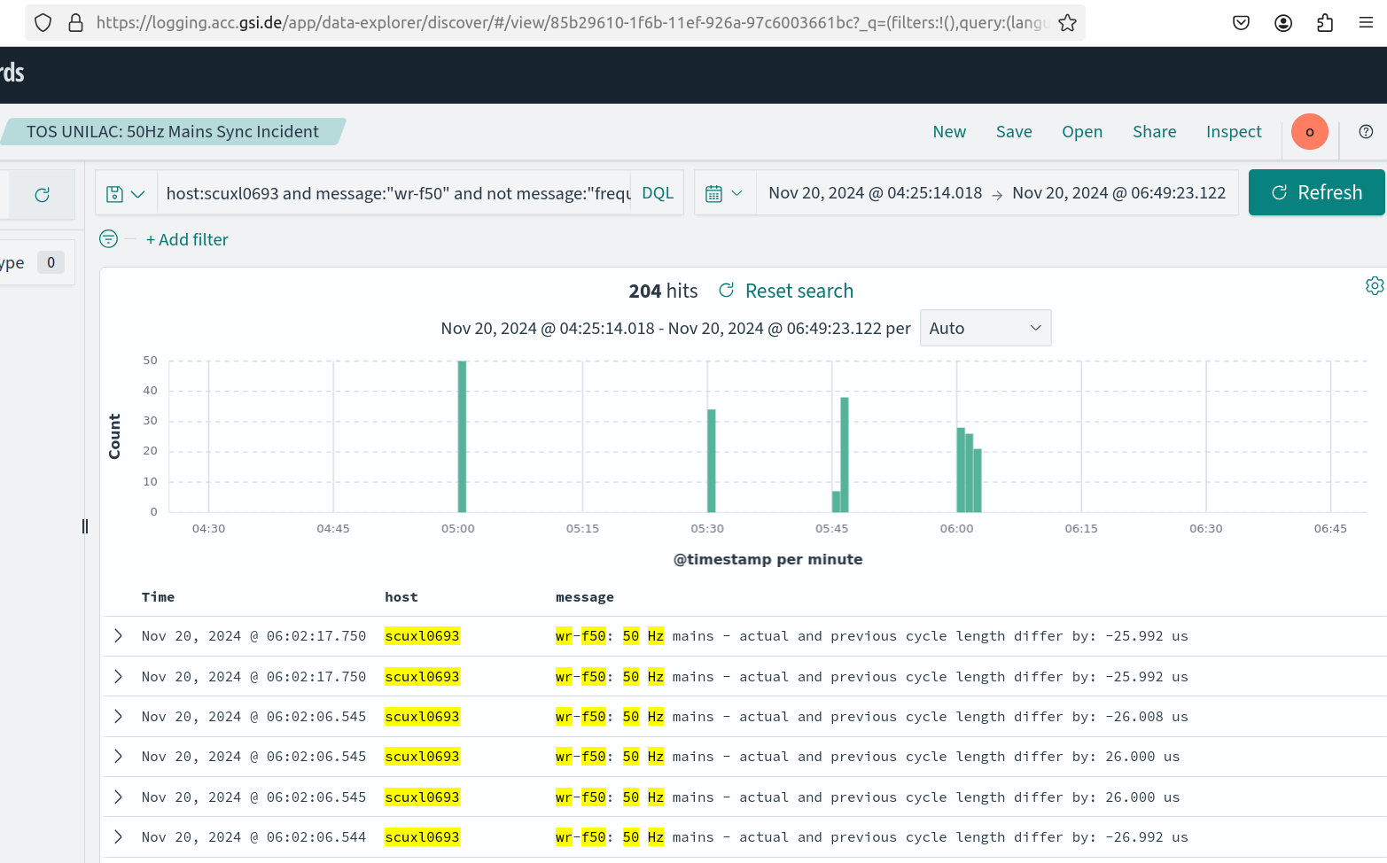
Usually, the standard deviation of the offset (UNILAC cycle start vs 50 Hz mains) is in the low one-digit microseconds range. However, the system is faced with unpredictable jumps of the 50 Hz mains. Those may happen, when switching is done by the mains network operation. Typically, this happens around quarters of an hour as shown in the figure below. Figure: Sudden jumps in the 50 Hz period.
Typically these jumps have a magnitude of 20-30 microseconds. However, larger jumps of up to 100 us are not uncommon.
-- DietrichBeck - 20 Nov 2024
 | I | Attachment | Action | Size | Date | Who | Comment |
|---|---|---|---|---|---|---|
| |
principle-synchronization.png | manage | 98 K | 19 Nov 2024 - 13:28 | DietrichBeck | principle of synchronization |
| |
unilac_50Hz_jitter.png | manage | 48 K | 20 Nov 2024 - 08:27 | DietrichBeck | variation of UNILAC cycle length |
| |
unilac_50Hz_jumps.png | manage | 203 K | 20 Nov 2024 - 09:59 | DietrichBeck | 50 Hz jumps |
| |
unilac_50Hz_sync_samples.jpg | manage | 315 K | 20 Nov 2024 - 08:35 | DietrichBeck | performance |
| |
wrf50-lsb6.JPG | manage | 155 K | 19 Nov 2024 - 08:36 | DietrichBeck | wr-f50 setup at LSB6 |
Edit | Attach | Print version | History: r6 < r5 < r4 < r3 | Backlinks | View wiki text | Edit wiki text | More topic actions
Topic revision: r6 - 20 Nov 2024, DietrichBeck
 Copyright © by the contributing authors. All material on this collaboration platform is the property of the contributing authors.
 Ideas, requests, problems regarding Foswiki? Send feedback


