|
|
You are here: Foswiki>Timing Web>TimingSystemDocumentation>TimingSystemHowTo>TimingSystemDeprecatedHowTo>TimingSystemHowToMiniCS (19 Jun 2019, DietrichBeck)Edit Attach
Timing System within miniCS
THIS HOWTO IS DEPRECATED After reflashing and upgrading the SCUs to 64bit, the timing system of release R1 is no longer operational! Thus, the information in this document is outdated! The system will be reinstalled/upgraded to release R4 after the milestone "ready for installation has been reached for CRYRING. Documentation of Timing System for miniCS (proton linac source)Status
- 00-Jul-2014: all SCUs reflashed and upgraded to 64bit. The timing system of release R1 no longer exists.
- 20-Sep-2013: timing system migrated to FESA3 and SL6 ("Frankreichnetz")
- 23-May-2013: timing system migrated into the environment prepared for Saclay
- 22-May-2013: link between application layer and FESA class of data master established
- 03-May-2013:
- Operational in the normal GSI network.
- Cycle with 4Hz repetition rate.
- Data Master implemented on SCU. FESA class implemented
- Timing Receiver on SCU: Delivery of pulses for magnetron including media converter copper->fiber
- Timing Receiver on VME: Delivery of cycle-start, pre-trigger, post-trigger and magnetron pulse as digital signal (TTL), no host-bus bridge. Link to Beam Instrumentation group via Lemo cables.
- All Timing Receivers: Configuration via timing network using a script from management server
FESA Class MCSTimingMaster
Interface
- GSI-Setting-Property: "Setting"
- cycleLength, length of cycle [us], a value of 250000 results in a repetion rate of 4 Hz, double
- pulseStartEventTime, time in [us] relative to cycle start. Allowed values are 0..cycleLength, double
- pulseStopEventTime, time in [us] relative to cycle start. Allowed values are 0..cycleLength, double
- preEventTime, time in [us] relative to cycle start. Allowed values are 0..cycleLength, double
- postEventTime,time in [us] relative to cycle start. Allowed values are 0..cycleLength, double
- nOfIterations, specifies how often a cycle is repeated. Values are 1..N. A value of -1 makes the cycle to iterate forever, int
- GSI-Setting-Property "ExpertSetting" (not yet implemented (May 2013))
- pulseStartEventID, default value 1: ID is a unique identifier used by the timing receiver to identify a timing message. pulseStart triggers the magnetron to produce protons, int
- pulseStopEventID, default value 2: ID is a unique identifier used by the timing receiver to identify a timing message. stopPulse indicates when the magnetron stops produce protons, int
- preEventID, default value 3: ID is a unique identifier used by the timing receiver to identify a timing message. preEvent is used by SD as a pre-trigger for the pulseStart, int
- postEventID, default value 4: ID is a unique identifier used by the timing receiver to identify a timing message. postEvent is used by SD as a post-trigger for pulseStart or pulseStop, int
- reserved1EventID, default value 5: ID is a unique identifier used by the timing receiver to identify a timing message. reserved1 is intended for future use, int
- reserved2EventID, default value 6: ID is a unique identifier used by the timing receiver to identify a timing message. reserved2 is intended for future use, int
- reserved1EventTime,time in [us] relative to cycle start. Allowed values are 0..cycleLength, default 0.0, double
- reserved2EventTime, time in [us] relative to cycle start. Allowed values are 0..cycleLength, default 10.0, double
- command-property "Command"
- dataMasterCommand, start (start producing beam), stop (stop beam production after actual cycle), break (stop beam production without finishing cycle, usw., enum DATAMASTER_COMMAND
- GSI-Acquisition-Property "Acquisition"
- cycleLengthSet, length of cycle [us], a value of 250000 results in a repetion rate of 4 Hz, double
- pulseStartEventTimeSet, time in [us] relative to cycle start. Allowed values are 0..cycleLength, double
- pulseStopEventTimeSet, time in [us] relative to cycle start. Allowed values are 0..cycleLength, double
- preEventTimeSet, time in [us] relative to cycle start. Allowed values are 0..cycleLength, double
- postEventTimeSet,time in [us] relative to cycle start. Allowed values are 0..cycleLength, double
- nOfIterationsSet, specifies how often a cycle is repeated. Values are 1..N. A value of -1 makes the cycle to iterate forever, int
- nOfIterationsAct, number of completed cycles since the last COMMAND_START, int
- dataMasterStateAct, status of data master, enum DATAMASTER_STATE
- acqStamp, time stamp of acquisition (time stamp obtained from timing network)
- cycleStamp, time stamp of beginning of actual cycle
- cycleName, name of actual cycle
- enum DATAMASTER_STATE, description: error; S0 (initial state); configured (must be configured before being started); started (producing beam); stopped (cycle finished an stopped); aborted (cycle aborted and stopped
- value="-1" symbol="DM_ERROR_UNKNOWN"
- value="0" symbol="DM_S0"
- value="1" symbol="DM_UNCONFIGURED"
- value="2" symbol="DM_CONFIGURED"
- value="3" symbol="DM_STARTED"
- value="4" symbol="DM_STOPPING"
- value="5" symbol="DM_STOPPED"
- value="6" symbol="DM_ABORTED"
- enum DATAMASTER_COMMAND, description: RECOVER (recover from error state); START (start producing beam); STOP (finish actual cycle and stop); ABORT (don't stop cycle and abort)
- value="-1" symbol="DATAMASTER_RECOVER"
- value="0" symbol="DATAMASTER_RESERVED"
- value="2" symbol="DATAMASTER_START"
- value="3" symbol="DATAMASTER_STOP"
- value="4" symbol="DATAMASTER_ABORT"
State Machine (SM)
Figure1 : State machine of the miniCS data master The state machine described here provides parallel states to the ones provided by the GSI default properties, and describes the status of the soft-processor in the FPGA of the data master. The prefixes "DM_ " and "DATAMASTER_" are omitted here. Allowed transitions are mentioned, except for the transition to state ERROR_UNKNOWN, which is allowed from all states In case of an severe error,
- S0: default state. After being started, the SM will transit to UNCONFIGURED on its own.
- implicit: NO_ERROR:
- UNCONFIGURED: After setting values of GSI-Setting-Properties "Settings" by the application, the SM transits to CONFIGURED on its own
- CONFIGURED:
- Upon request by the application via the command START, the SM transits to state STARTED
- After setting values of GSI-Setting-Properties "Settings" by the application, the SM make a self-transition to CONFIGURED on its own
- STARTED:
- Upon request by the application via the command STOP, the SM transits to state STOPPING
- Upon request by the application via the command ABORT, the actual cycle is aborted and the SM transits to state ABORTED
- If the cycle has been repeated for the specified number of iterations, the SM transits to state STOPPED
- STOPPING:
- Upon request by the application via the command ABORT, the actual cycle is aborted and the SM transits to state ABORTED (might be useful if a the length of a cycle takes minutes or hours)
- the SM waits until the actual cycle is completed, afterwards it transits to state STOPPED
- STOPPED, ABORTED
- Upon request by the application via the command START, the SM transits to state STARTED, reiterating through the cycles specified in the configuration.
- After setting values of GSI-Setting-Properties "Settings" by the application, the SM transits to state CONFIGURED.
- ERROR_UNKNOWN: error state.
- In case of a severe error, the SM may transit to this state from all other states
- Upon request by the application via the command RECOVER, the SM transits to state UNCONFIGURED
Libraries (cheat!)
File Structure on the Management Server
The important stuff for the timing system is in a folder ~/timing[france@frl001 timing]$ ll total 20 drwxrwxr-x 2 france france 4096 May 22 15:07 allerlei -rwxrwxr-x 1 france france 460 May 22 12:30 bash_dietrich.sh -rwxrwxr-x 1 france france 432 May 22 12:19 bash_dietrich.sh~ drwxrwxr-x 3 france france 4096 May 22 12:28 mcs-bin drwxrwxr-x 3 france france 4096 May 23 12:09 mcs-conf [france@frl001 timing]$The items shown are the following
- allerlei: reserved for timing system
- mcs-conf: contains configuration script and configuration file for timing receivers. This folder is under version control: https://www-acc.gsi.de/svn/bel/timing/trunk/configuration/mcs-conf .
- mcs-bin: contains binaries used by the configuration script. This folder is under version control: https://www-acc.gsi.de/svn/bel/timing/trunk/production/miniCS/i386/bin .
- bash_dietrich.sh: using "source bash_dietrich.sh" is not required for the configuration of timing receivers. It is only useful for debugging.
Configuration of Timing Receivers
For FAIR, a typical front-end consists of FEC including a host system. FESA software is used on the host system to control and monitor equipment via the interfaces of the front-end. In some cases, one of the interfaces will be a timing receiver. The timing receiver is configured by the FESA software, which receives set-values for the timing receiver's configuration from the settings management. For the miniCS, the the FESA software on the front-ends including timing receivers does not take care of the configuration of timing receivers. At least, this is not foreseen (May 2013). Hence, the timing receivers are configured via the timing network from the management server.How-To Configure Timing Receivers
Logon to the management server frl001 using ssh. Thencd timing/mcs-conf ./init-minics.shThis needs to be done every time after a timing receiver has been power cycled. The script ini-minics.sh configures the timing receivers via the timing network. The script uses a configuration file minics.conf, which is a text file in the same folder. Binaries required by the script are in folder ../mcs-bin.
Debugging
Display Info
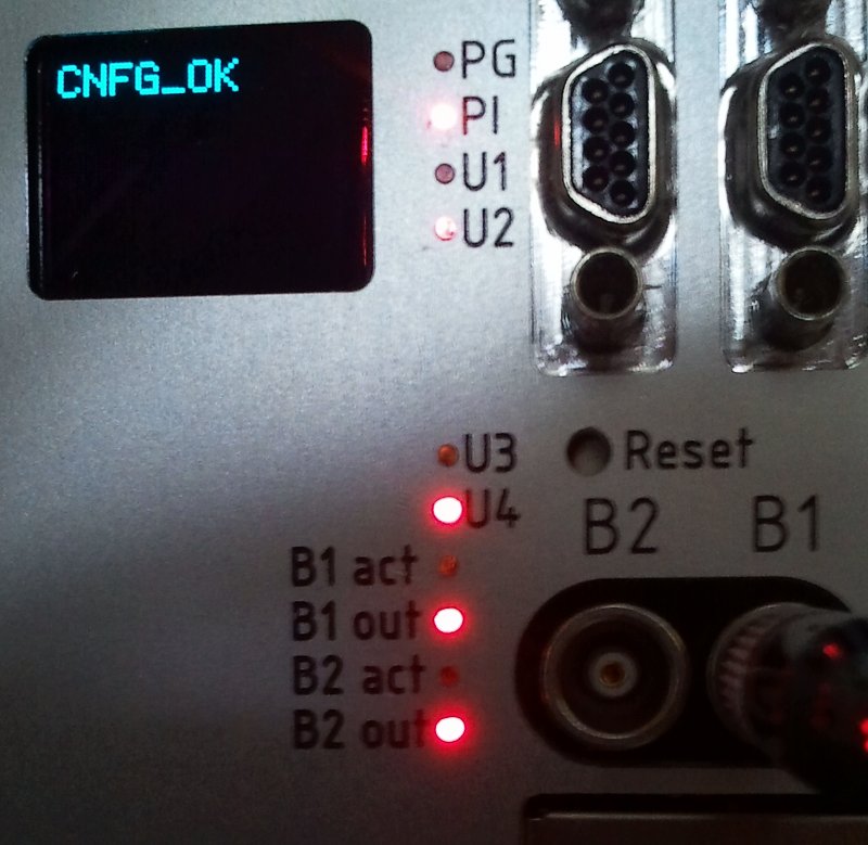
Fig 2 : Example front panel of an SCU configured as timing receiver(see text).
Figure 2 shows the front panel of an SCU configured as timing receiver.
- Display: If configured, the display says "CNFG_OK"
- U LED1: Indicates PPS pulse (Pulse Per Second)
- U LED1: Indicates activity on the White Rabbit link
- Bn out: direction of Lemo Bn in (unlit) or out (lit)
- B1 ACT: Indicates activity of Lemo B1. Here: timing-event as digital pulse
- B2 ACT: Indicates activity of Lemo B2. Here: PPS Pulse
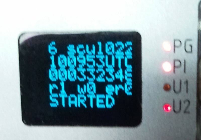
Fig 3 : Example of front panel of SCU configured as data master (see text).
Figure 3 shows the display of an SCU configured as data master. The lines of the display contain the following information.
- some info
- state of White Rabbit link. o.k. "2": PPS is valid, "4" timestamp is valid, "6"="4"+"2": link is o.k
- host name of SCU
- hhmmssUTC: UTC time within the White Rabbit network. The time is propagated from a clock master (WR switch) to the nodes.
- cycle counter, number of completed machine cycles.
- status display of data master softcore on lm32 in FGBAas boolean values
- "r?": is running
- "w?": is waiting on an external condition
- "er?": has detected an error
- status of the state machine of the FESA class.
Low Level Debugging
Timing Switch
Logon to timing switch might be useful to see remotely, which ports are in use "wr_mon" or to check which devices are connected to what port "rtu_stat". It is also possible to reboot a switch remotely.IT Infrastructure
- bootp activity: "cat /var/log/dnsmasq/dnsmasq-yyyy-mm-dd | grep eth2"
- dhcp activity: "cat /var/log/dnsmasq/dnsmasq-yyyy-mm-dd | grep eth1"
Using the Etherbone Tools
This is really for experts getting their hands dirty. Some debugging on the timing system can be done by using the Etherbone tools. First you need to set some paths. Run[france@frl001 ~]$ source timing/bash_dietrich.shto set LD_LIBRARY_PATH and PATH for the Etherbone tools. At this point it might be a good idea to find out about nodenames and IPs in the network. Then the usual tools like "eb-ls udp/scul024ft.fr" should work.
- eb-read udp/scul024ft.fr 0x3d00c/4 : status register of data master (mask 0x08: has error, 0x1 debug mode, 0x2: is running, 0x8 is waiting
- eb-write udp/scul024ft.fr 0x3d000/4 : command register of data master (cmd 0x01000000: start, 0x02000000: start in debug mode, 0x04000000: stop, 0x08000000: abort)
Edit | Attach | Print version | History: r14 < r13 < r12 < r11 | Backlinks | View wiki text | Edit wiki text | More topic actions
Topic revision: r14 - 19 Jun 2019, DietrichBeck
Ideas, requests, problems regarding Foswiki? Send feedback