You are here: Foswiki>FESA Web>WhatIsFESA (05 Sep 2019, SolveighMatthies)Edit Attach
What is FESA ?
The software running in the front-end equipment controllers (FECs) will be developed using an adequate front-end framework, called FESA. This framework is a complete environment for software developers to design, develop, test and deploy software for the FECs. FESA stands for F(ront)E(nd)S(oftware)A(rchitecture)Overview
The picture below shows where in the different control-system layers FESA is located. FESA software use many communication-channels to other control-system components. This picture illustrates the most common channels:- The operators in the control room communicate with FESA software via the acc-network by using the cmw-middleware.
- FESA software communicates to hardware devices via any kind of bus-system (dependent on the hardware type).
- The timing master synchronizes the operation of different accelerator devices driven by FESA software with each other, so that each accelerator device performs its beam interactions at the right time. At GSI the White Rabbit Timing is used for this purpose.

Basic Principles
There are some basic principles used in FESA:- Accelerator devices are represented as software devices
- Standardized front-end software development
- The whole front-end software follows the same API --> Easy to maintain
- Not only the developer of a class is able to debug
- Enable front-end software development for everybody
- Each GSI-section can contribute
- Flexibility
- Extensibility
Components
A FESA binary consists of a couple of sub-components:- Any number of "FESA classes", each describing a device-type
- Any number of "Properties" can be used to provide an API for clients (e.g. the operators)
- For productive software operations expect a standard set of properties
- Internal data, actions, event-sources, etc. can be defined and filled with code
- Each FESA class can handle any number of "device instances", each describing a concrete device
- Device-Specific configuration can be configured in an xml-file, the so called "instance-file"
- As well the events-mapping and the priority management can be configured per device
- A "FESA Deployment Unit" is used in order to coordinate the different FESA classes
- This includes action-scheduling and a default priority management
Internal Structures
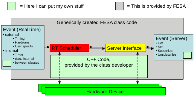
In order to ease class-development, the class-developer defines the design of his FESA-class in an xml-file. According to the defined class, FESA automatically generates C++ source-code in a way that mainly hardware-interactions have to filled by the class-developer. ( The picture below shows the possibilities to add user-code in light green. ) FESA binaries are logically separated into two blocks, the "RT-Part" (realtime part) and the "Server-Part". The Server-Part takes care for any client(operator)-communication, while the RT-Part focuses on hardware-interactions. If required, both parts can be run in split mode as separate binaries. The RT-part schedules all actions which can be performed by a device. There are different trigger-sources ("event-sources") which can trigger these actions. There are external event-sources, like the White Rabbit Timing and hardware-specific triggers and there are internal Event-Sources, like a timer, triggers from the Server-Part or inter-class-triggers. All of these triggers can execute the class-specific C++ code defined in a action. The Server-part implements the API of the cmw-middleware in order to establish client-communication. "Get" can be used to read out property/device-specific information. Via "Set" device-specific property-values can be changed and via "Subscribe"/"Unsubscribe" a client can register to be notified whenever a property changes for a specific device.
Edit | Attach | Print version | History: r6 < r5 < r4 < r3 | Backlinks | View wiki text | Edit wiki text | More topic actions
Topic revision: r6 - 05 Sep 2019, SolveighMatthies
 Copyright © by the contributing authors. All material on this collaboration platform is the property of the contributing authors.
 Ideas, requests, problems regarding Foswiki? Send feedback
