|
|
You are here: Foswiki>BunchBucket Web>BunchBucketDocumentation>BunchBucketDocuments>BunchBucketLightProofOfPrincipleSetup (11 Jan 2022, DietrichBeck)Edit Attach
Proof-of-Principle: Setup at SIS18 and ESR
Table of ContentsIntroduction
The idea is to setup and perform a proof-of-principle machine experiment in the 2021 beam time. This page describes the hardware setup and status.Idea
Basically, the B2B system will replace the so-called 'Timing-Generator' which is installed in one of the racks in the SD-Cage in BG 2.009.- only the 'trigger cable' to the kicker control electronics will be swapped from 'Timing-Generator' to the B2B-system
- the B2B electronics will be installed in the kicker rooms: swapping of trigger cables is also done in the kicker rooms
- according to Alexander Bauer, the electronics requires 2V as input level
- it is assumed that the output of a PCIe Timing Receiver can drive the input of the electronics directly
- model and LSA make rules should not be touched; this ensures that the kickers will be controlled (loaded in time, etc) as before
- EVT_KICK_START is important for B2B
- in case RF-synchronization is required, this event will trigger the B2B system but not the kickers
- in case RF-synchronization is NOT required, this event will trigger the kickers, but not the B2B system
- this will be changed for the 2022 beam time
- LSA data supply
- not for 2021
- the LSA values of the RF frequencies must be supplied 'by hand / CLI'
- the LSA values for the extraction mode (kicker fired directly or after RF-synchronization) must be supplied 'by hand / CLI'
Overview
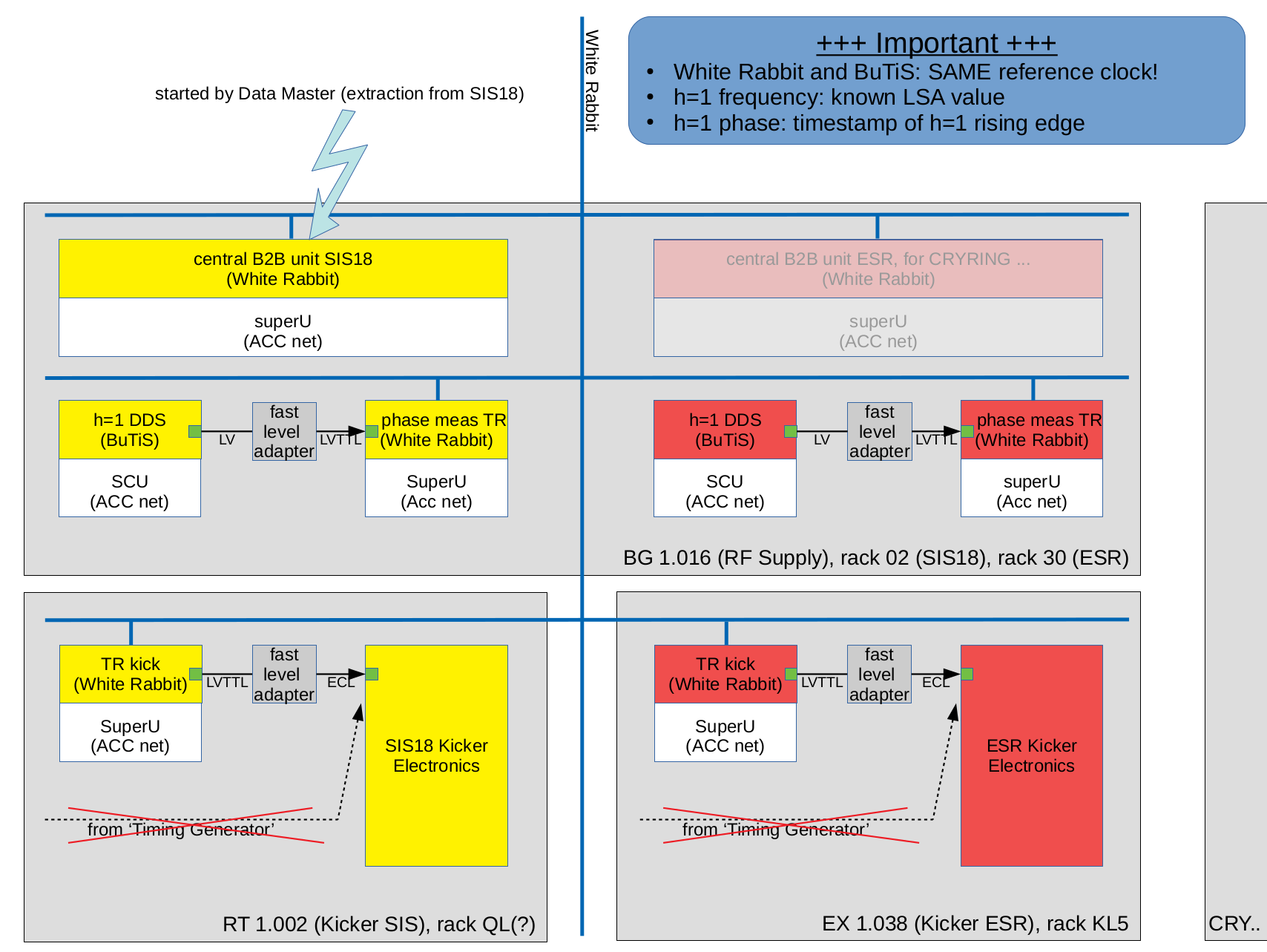 Figure: Overview on prime components of the components for the B2B light system. Shown are components for SIS18 (red), ESR (yellow), rooms (gray) and the White Rabbit network (blue lines). Details see text.
For an extraction from SIS18, its Central B2B Unit (CBU) is triggered by the Data Master. The CBU knows the H=1 frequencies of SIS18 and ESR as well as the harmonic numbers. These are sent via the White Rabbit network to the Phase Measurement Timing Receivers (PM), where White Rabbit timestamps of the DDS H=1 signals are measured. The PM send the timestamps to the CBU. In case of a B2B transfer using 'frequency beating', the CBU calculates the time in the future (~ms) when phases of SIS18 and ESR will match. Ahead of time, the CBU sends this information to the Kick Timing Receivers. Those take into account known fixed delays and create LVTTL signals that are used to directly trigger the kicker electroncis firing the kicker. The CBU for ESR is not needed for the transfer from SIS18 to ESR; it vaguely indicates a follow-up transfer to CRYRING.
Figure: Overview on prime components of the components for the B2B light system. Shown are components for SIS18 (red), ESR (yellow), rooms (gray) and the White Rabbit network (blue lines). Details see text.
For an extraction from SIS18, its Central B2B Unit (CBU) is triggered by the Data Master. The CBU knows the H=1 frequencies of SIS18 and ESR as well as the harmonic numbers. These are sent via the White Rabbit network to the Phase Measurement Timing Receivers (PM), where White Rabbit timestamps of the DDS H=1 signals are measured. The PM send the timestamps to the CBU. In case of a B2B transfer using 'frequency beating', the CBU calculates the time in the future (~ms) when phases of SIS18 and ESR will match. Ahead of time, the CBU sends this information to the Kick Timing Receivers. Those take into account known fixed delays and create LVTTL signals that are used to directly trigger the kicker electroncis firing the kicker. The CBU for ESR is not needed for the transfer from SIS18 to ESR; it vaguely indicates a follow-up transfer to CRYRING.
Shopping List for Beam-Time 2021
This is completed. See here.Shopping List for Beam-Time 2022
Common
- reshuffle SuperU
- RT 1.002: proper installation of SuperU
- fast comparator upgrade and commissioning
- firmware upgrade and commissioning
- ToDo-List (click)
SIS and ESR Kicker Rooms
- RT 1.002,
 : 2 ports needed (2 TR)
Triggering of MIL Based Equipment
see hereMain Control Room
- White Rabbit based kicker trigger signal for B2B system at ESR console; required?
- White Rabbit based kicker trigger signal elsewhere?
CRYRING Extension, planning 2022, to be updated
- ACC Network
- Cave, : 4 ports needed (2 SuperMicro)
- TH.2.'RF': : 4 ports needed (1 SuperMicro CBU+PM)
- Cave,
- WR Network
- Cave, , additional 24 ports (container <-> cave)
- B2B requires 4 ports needed (2 Kicker, 2 Diagnose)
- 20 ports backup for ACC, experiments
- TH.2.031a, : 4 ports needed (1 SCU, 2 TR, 1 diagnose)
- Cave,
- SuperMicro: 3
- Cave,
 : 2 (Kick Injection, Kick Extraction)
- TH.2.031a, : 1 (CBU+PM)
- Cave,
- PCIe TR (Pexaria or PexP): 6
- Cave, : 4 (Kick Injection, Kick Extraction, Diagnose)
- TH.2.031a, %ICONY%: 2 (CBU+PM)
- Cave,
- SCU
- TH.2.031a, : 1 'Gruppen DDS'
- TH.2.031a,
Simplified Supply with Set-Values
Multiplexing
Today (November 2020) the FECs for kicker control are still based on DeviceAccess. Thus, multiplexing is limited to Sequence IDs 0..15. Multiplexing is entirely implemented in the firmware of the CBU. The multiplexing data can be loaded into the firmware far ahead of the execution time. Real-time is not required.CLI
Today (November 2020) there is only an extremely simple command line interface. The data that need to be supplied are basic.-
seth1inj < freq > < h >set h=1 frequency [Hz] and harmonic number of injection machine -
seth1ext < freq > < h >set h=1 frequency [Hz] and harmonic number of extraction machine -
setgid < GID >set Group ID of B2B transfer ('0x3a1') -
setsid < SID >set Sequence ID of schedule in extraction machine; allowed range is 0x0..0xf -
setmode < SID >set mode- 0: off
- 1: EVT_KICK_START; extraction kicker is triggered on EVT_KICK_START
- 2: bunch to extraction; extraction from ring; triggered on group DDS h=1 signal
- 3: bunch to coasting; transfer to another ring as coasting beam; extraction is triggered on group DDS h=1 signal
- 4: bunch to bucket; presently only frequency beating of the two DDS h=1 signals is supported
-
setcphase < offs >set correction for phase matching [ns] -
setctrigext < offs >set correction for trigger kicker extraction [ns] -
setctriginj < offs >set correction for trigger kicker injection [ns]
- other (to be decided)
- adressing invidual bunches/buckets
- what about h=1/n ? This makes no sense from the physics point of view, but sometimes the Group DDS is operated below revolution frequency for special purposes
-
submitsubmits a complete set of values that have been set (see above) -
clearconfigclears configuration data for all (0x0..0xf) Sequence IDs
LSA and Data Supply
Concept- each extracting machine has its own CBU: SIS18 and ESR (CRYRING maybe in the future)
- the extraction process is started on event
- beam time 2021
- SIS18: EVT_KICK_START_1 (0x31)
- ESR: EVT_KICK_START_2 (0x45)
- beam time 2022
- ???
- beam time 2021
- delay of extraction
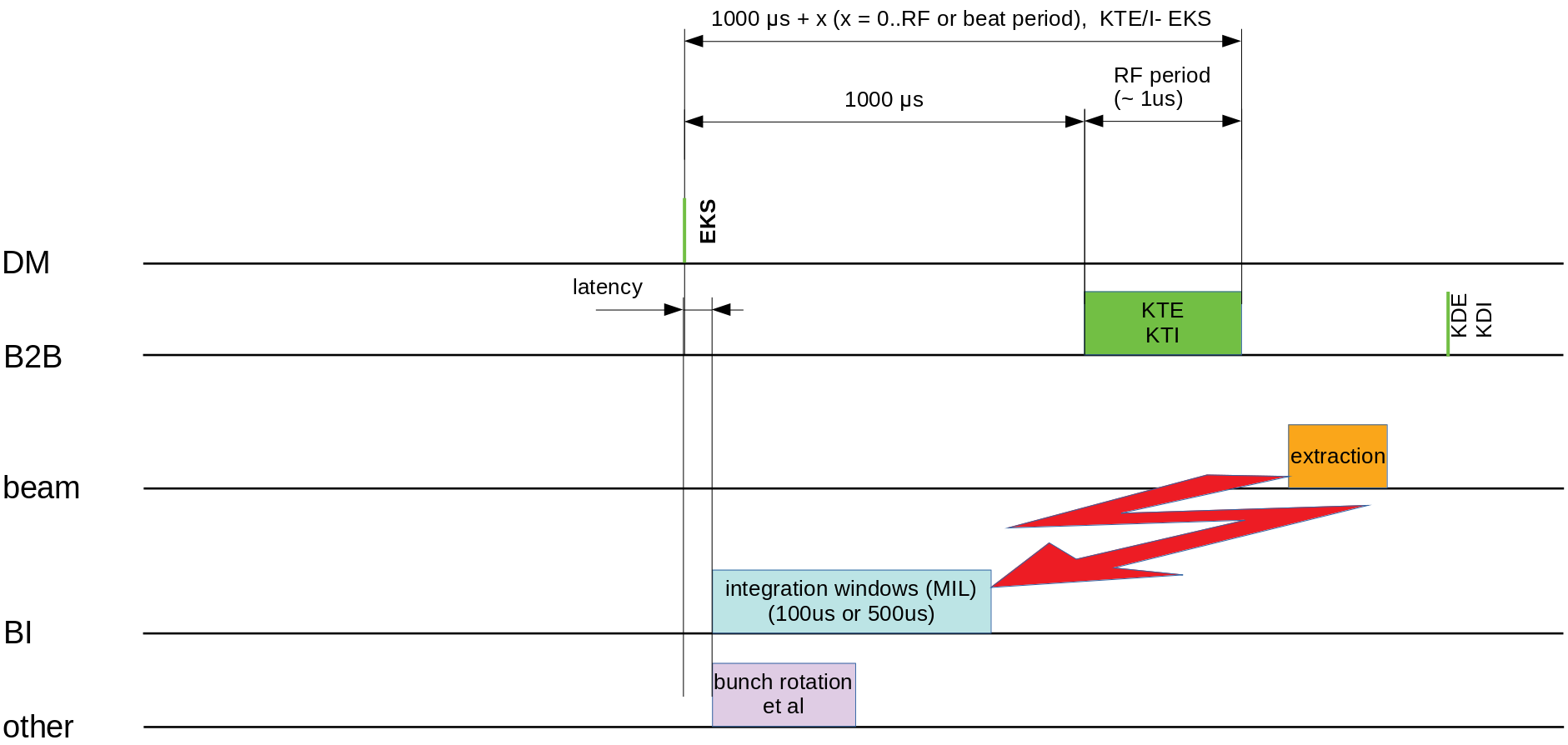
- mode 1: 0 us
- mode 2: 1000 + x us; x is in a range of 0..T; where T is the period of H=1; Thus, the extration machine must stay on the flat top for at least 1ms after EVT_KICK_START.
- mode 3: same as for mode 2
- mode 4: time of extraction is in a range of 1..11 ms, required the beating frequency is <10 ms
- the B2B system guarentees that the extraction/transfer is finished within the times mentioned above
- the B2B system provides the following 'special events' that might be of interest (see event numbers)
- CMD_B2B_TRIGGEREXT
- trigger kicker electronics (extraction)
- SID equals the one of EVT_KICK_START, GID equals GID of the extraction ring
- CMD_B2B_TRIGGERINJ
- trigger kicker electronics (injection)
- SID equals the one of EVT_KICK_START, GID equals GID of the injection ring
- event is played only for modes 3 and 4
- CMD_B2B_DIAGKICKEXT
- real-time kick diagnostic (extraction)
- SID equals the one of EVT_KICK_START, GID equals GID of the extraction ring
- provides information on exact kicker time acquired in real-time
- event is played exactly 1ms after CMD_B2B_TRIGGEREXT
- CMD_B2B_DIAGKICKINJ
- real-time kick diagnostic (injection)
- SID equals the one of EVT_KICK_START, GID equals GID of the injection ring
- provides information on exact kicker time acquired in real-time
- event is played exactly 1ms after CMD_B2B_TRIGGERINJ
- event is played only for modes 3 and 4
- CMD_B2B_TRIGGEREXT
- (ACC nomen for CBU shall be 'located' at the ring)
- set values
- mode, 0..4
- SID, 0..15
- GID of injection machine (only for modes 3 and 4)
- h=1 frequency [Hz] and harmonic number of extraction machine
- h=1 frequency [Hz]and harmonic number of injection machine (only for modes 3 and 4)
- correction for phase matching
- specifies requested phase difference for frequency beating (default 0 ns)
- only for mode 4
- this is the 'phase tune knob' for the operators
- the firmware requires a value [ns]
- correction for extraction kicker trigger
- specifies 'offset' of extraction kicker timing
- this is the 'find/tune bunch gap knob' for the operators
- the firmware requires a value [ns]
- correction for injection kicker trigger
- specifies 'offset' of injection kicker timing
- this is the 'find/tune bunch gap knob' for the operators
- the firmware requires a value [ns]
- other (to be discussed, see CLI above)
- addressing individual bunches/buckets
- h = 1/n
FESA Class
This basically just needs push and submit a set of ~8 values to the firmware. This needs to be done, if data is supplied for a specific SID. In case LSA choses different units for the three corrections, the values need to be converted to [ns]. A CLI is present on the frontend. In the simplest case, the values could be written to the firmware by just using 'system' calls from FESA. -- DietrichBeck - 11 Jan 2022

| I | Attachment | Action | Size | Date | Who | Comment |
|---|---|---|---|---|---|---|
| |
Screenshot from 2020-06-08 15-44-09.png | manage | 190 K | 15 Jun 2020 - 08:35 | DietrichBeck | rooms and equipment |
| |
b2b-trigger-2021.png | manage | 72 K | 26 May 2021 - 11:32 | DietrichBeck | b2b trigger 2021 |
| |
b2b-trigger-2022.png | manage | 65 K | 09 Dec 2021 - 08:10 | DietrichBeck | b2b trigger 2022 |
Edit | Attach | Print version | History: r23 < r22 < r21 < r20 | Backlinks | View wiki text | Edit wiki text | More topic actions
Topic revision: r23 - 11 Jan 2022, DietrichBeck
- Toolbox
-
 Create New Topic
-
 Index
Index
-
 Search
-
 Changes
-
 Notifications
-
 RSS Feed
-
 Statistics
-
 Preferences
Ideas, requests, problems regarding Foswiki? Send feedback