You are here: Foswiki>Machines Web>MachineUNILAC>UnilacBeamLossMonitoringSystemFirstPlanningMeeting (12 Dec 2024, PeterGerhard)Edit Attach
Initial Meeting on Project Planning for the new UNILAC Beam Loss Monitoring System
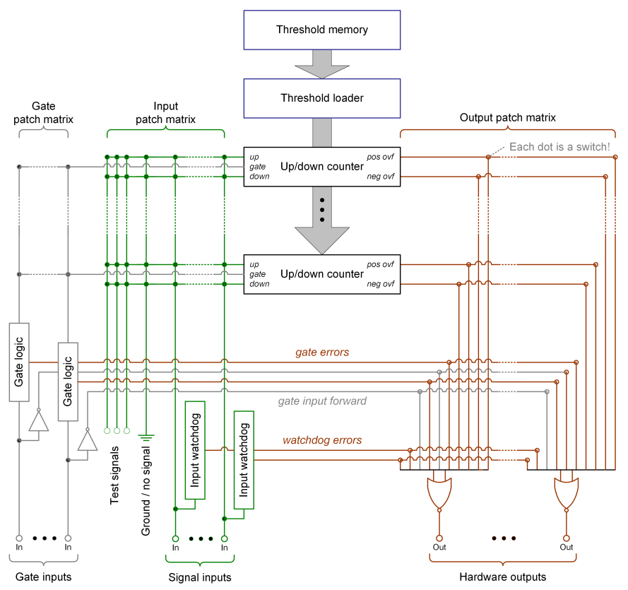
Date: 2024-12-05 Participants: Michał Dziewiecki, Peter Gerhard, Tobias Habermann, Hanno Hüther, Karim Laihem Minutes: Hanno Hüther Michał introduced the basic ideas and design principles behind (the hardware-layer of) the new BLM system for UNILAC. He frequently referred to the block diagram from the BLM system's documentation (shown below), explaining how it is comprised of inputs, counters and outputs configured by datasets and structured into groups. Michał specified that a total number of 54 trafo inputs, 12 input gates, 128 counters, 6 outputs, 32 datasets and 16 groups are available per crate. Currently, he is planning for 2 crates to be installed, but if that would prove insufficient, it might be possible to install 3 crates depending on available rack space. Peter stated that in order to be compatible with the current chopper control hardware, 4 outputs are required for beam loss signals and an additional 4 outputs for profile grid protection signals, which would mean that at least 2 crates are required.
As far as it can be determined after a quick and rather superficial assessment based on the information provided, the new beam loss monitoring system hardware seems to be appropriate in principle for replacing the existing legacy hardware. However, there is still some concept work to be done regarding assignment of the individual components (inputs, counters, outputs, groups) to ensure that it actually delivers the required functionality. A more reliable statement can be made after a proposal for concrete configuration has been established. This requires contributions from UNILAC and/or beam diagnostics experts. (PG: For the moment I do not see a requirement for BD experts)
- clarify coordination of BLM and cups, to me this is unclear even for the legacy system; maybe this is no problem because there are no cups within the monitored areas of the UNILAC so far?
- proposal tbd for adding some safety and solve the problem of deactivating unnecessary/unwanted loss monitors:
- LSA provides thresholds for all monitors within context AND transferline
- Front End contains look-up table (may be hardcoded or generated somehow) of all available monitors and their transferline memberships; this table has to be supervised and maintained by the person in charge of the hardware together with its counterpart for the front end, because they know what monitors are actually connected to the system
- this enables the Front End to 1) cross-check the monitors which have been provided thresholds by LSA for a certain context with its own list of monitors attached to the corresponding transfer line, and 2) disable the monitors which are not part of the transfer line
- how to check/monitor that the connected monitors (i.e. beam transformers) are live?
| I | Attachment | Action | Size | Date | Who | Comment |
|---|---|---|---|---|---|---|
| |
2024-12-05_unilac_blm_system.pdf | manage | 1 MB | 06 Dec 2024 - 15:34 | HannoHuether | |
| |
unilac_blm_system_block_diagram.png | manage | 123 K | 06 Dec 2024 - 15:38 | HannoHuether |
Edit | Attach | Print version | History: r5 < r4 < r3 < r2 | Backlinks | View wiki text | Edit wiki text | More topic actions
Topic revision: r5 - 12 Dec 2024, PeterGerhard
 Copyright © by the contributing authors. All material on this collaboration platform is the property of the contributing authors.
 Ideas, requests, problems regarding Foswiki? Send feedback


