|
|
You are here: Foswiki>BunchBucket Web>BunchBucketDocumentation>BunchBucketDocuments>BunchBucketSetup (23 Jun 2023, DietrichBeck)Edit Attach
Setup
Table of ContentsSchematic View
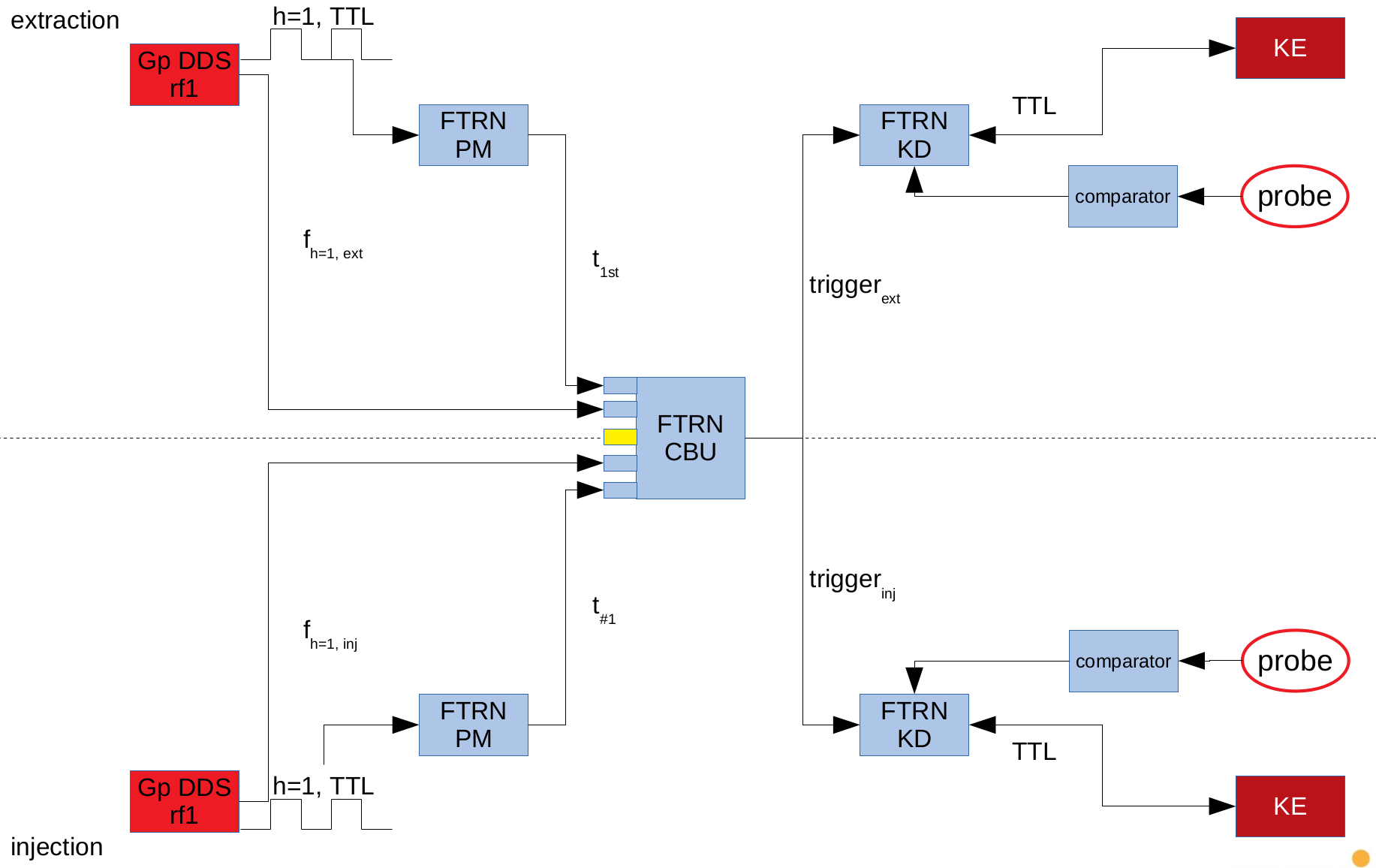 Figure: Extraction (top) and injection (bottom).
The figure above depicts the setup. Group DDS system generate H=1 clock signals of which the phase is measured at Phase Measurement TR (PM). The values are transferred to the CBU, where matching is achieved. Then, the CBU broadcasts a trigger message via the timing network. Dedicated TR vor Kick and Diagnostics (KD) trigger the kicker electronics. Signals from the kicker electronics and kicker magnet probe are timestamped for further processing. From the hardware point of view, all components in the above figure are standard components (only the comparator is a custom build).
At present SCUs (Arria II FPGA) only provide 8ns granularity and slow I/Os, the hardware for PM, CBU and KD are TR in form-factor PCIe (Arria V FPGA) that provides 1ns timing granularity with I/Os supporting LVTTL signals with risetime/falltime below 1ns into 50 Ohm. The TR are mounted in 1U servers. No special FPGA gateware is used. All TRs use the regular gateware of the current release of the timing system. The regular gateware includes a LM32 softcore in HDL that allows users to run firmware (C code) in hard real time on the FPGA. An example for such firmware is the 'function generator' for ramping magnets or RF systems. The 'glue' that converts the TR into modules for B2B is a dedicated firmware that is loaded into the LM32 at run-time.
Figure: Extraction (top) and injection (bottom).
The figure above depicts the setup. Group DDS system generate H=1 clock signals of which the phase is measured at Phase Measurement TR (PM). The values are transferred to the CBU, where matching is achieved. Then, the CBU broadcasts a trigger message via the timing network. Dedicated TR vor Kick and Diagnostics (KD) trigger the kicker electronics. Signals from the kicker electronics and kicker magnet probe are timestamped for further processing. From the hardware point of view, all components in the above figure are standard components (only the comparator is a custom build).
At present SCUs (Arria II FPGA) only provide 8ns granularity and slow I/Os, the hardware for PM, CBU and KD are TR in form-factor PCIe (Arria V FPGA) that provides 1ns timing granularity with I/Os supporting LVTTL signals with risetime/falltime below 1ns into 50 Ohm. The TR are mounted in 1U servers. No special FPGA gateware is used. All TRs use the regular gateware of the current release of the timing system. The regular gateware includes a LM32 softcore in HDL that allows users to run firmware (C code) in hard real time on the FPGA. An example for such firmware is the 'function generator' for ramping magnets or RF systems. The 'glue' that converts the TR into modules for B2B is a dedicated firmware that is loaded into the LM32 at run-time.
Topology
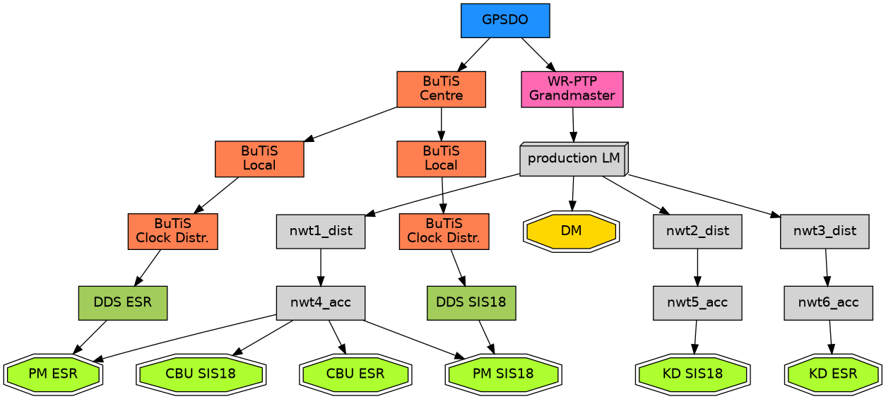 Figure: Simplified sketch of White Rabbit Network (gray) and BuTiS clock distribution (coral) relevant for the B2B system at SIS18 and ESR. The figure shows the location/relation of the Local Master Switches (LM), Data Master (gold), White Rabbit Grandmaster Switch (pink), B2B nodes (light green) and group DDS (dark green). Nodes that may send messages to the timing network are marked by hexagons. The connecting black arrows indicate the direction of clock propagation. The flow of data might be bi-directional.
The figure above shows a simplified sketch of the White Rabbit und BuTiS clock distribution networks. The nodes relevant for the B2B system are shown in light green, Central B2B Unit (CBU), Phase Measurement (PM) and Kicker trigger and Diagnostics (KD) for the two rings SIS18 und ESR. More detailed information is given on an internal page.
Figure: Simplified sketch of White Rabbit Network (gray) and BuTiS clock distribution (coral) relevant for the B2B system at SIS18 and ESR. The figure shows the location/relation of the Local Master Switches (LM), Data Master (gold), White Rabbit Grandmaster Switch (pink), B2B nodes (light green) and group DDS (dark green). Nodes that may send messages to the timing network are marked by hexagons. The connecting black arrows indicate the direction of clock propagation. The flow of data might be bi-directional.
The figure above shows a simplified sketch of the White Rabbit und BuTiS clock distribution networks. The nodes relevant for the B2B system are shown in light green, Central B2B Unit (CBU), Phase Measurement (PM) and Kicker trigger and Diagnostics (KD) for the two rings SIS18 und ESR. More detailed information is given on an internal page.
Kicker and Diagnostics
SIS18 and ESR
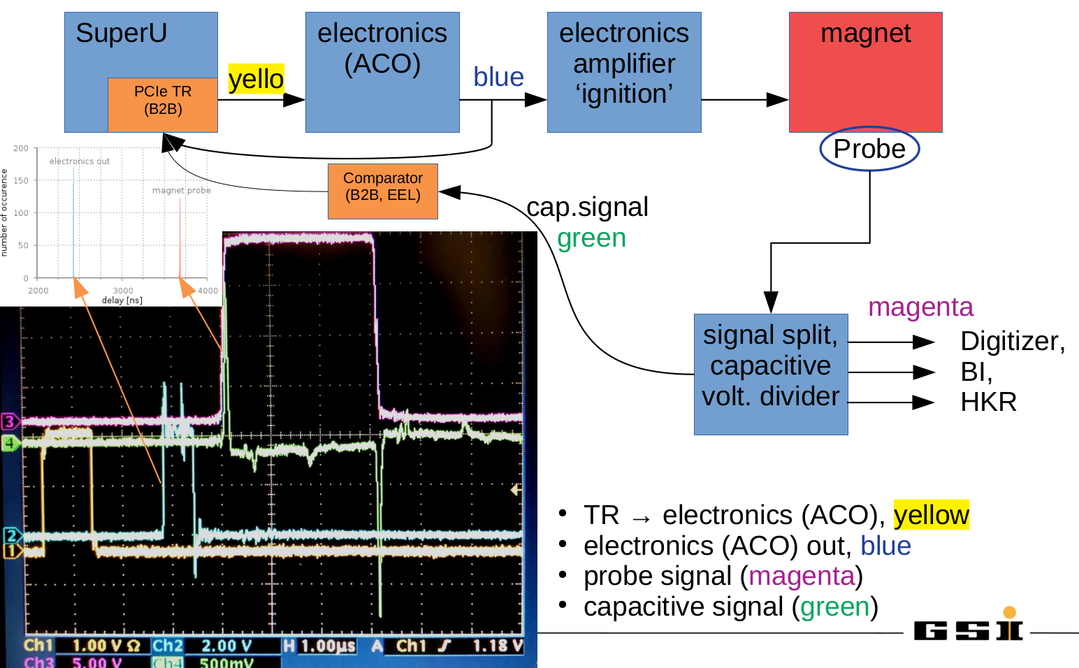 Figure: Kicker signals and diagnostics. The figure on the oscilloscope screen show the following signals: Trigger from B2B (yellow), output from ACO electronics (blue), kicker magnet probe (magenta) and kicker magnet probe obtained via a capacitive voltage divider (green). Details see text.
The Bunch-2-Bucket system sends a timing message with CMD_B2B_TRIGGEREXT (not shown) to the Timing Receiver (TR) mounted in a 1U server. On-time, the TR creates a LVTTL signal (yellow) that is fed into a first set of electronics modules (this signal replaces the one from the famous 'Timing Generator'). The electronics performs certain tasks including the generation of a TTL signal (blue) that is fed into the main kicker electronics. When this happens, the kicker ignites and the kicker magnet is energized. A pickup probe allows to monitor the magnetic field at the kicker magnet. The probe signal is split and feeds various customers (magenta). The special feature of importance here is a capacitive voltage divider. A fast comparator is used to convert the output of the voltage divider signal to LVTTL (green). The bunch-2-bucket system uses the rising edges of signals for various purposes.
Figure: Kicker signals and diagnostics. The figure on the oscilloscope screen show the following signals: Trigger from B2B (yellow), output from ACO electronics (blue), kicker magnet probe (magenta) and kicker magnet probe obtained via a capacitive voltage divider (green). Details see text.
The Bunch-2-Bucket system sends a timing message with CMD_B2B_TRIGGEREXT (not shown) to the Timing Receiver (TR) mounted in a 1U server. On-time, the TR creates a LVTTL signal (yellow) that is fed into a first set of electronics modules (this signal replaces the one from the famous 'Timing Generator'). The electronics performs certain tasks including the generation of a TTL signal (blue) that is fed into the main kicker electronics. When this happens, the kicker ignites and the kicker magnet is energized. A pickup probe allows to monitor the magnetic field at the kicker magnet. The probe signal is split and feeds various customers (magenta). The special feature of importance here is a capacitive voltage divider. A fast comparator is used to convert the output of the voltage divider signal to LVTTL (green). The bunch-2-bucket system uses the rising edges of signals for various purposes. - electronics out
- signal is active: confirmation the electronics is supplied with settings data and the kicker is active
- monitoring of the set-value of the delay that has been set for the kicker
- probe signal
- signal is active: indication, that the full kicker scenario is working
- monitoring of the real kick time
CRYRING
The setup is similar to SIS18 and ESR. As the main differences, the CRYRING kicker is implemented with a modern SCU architecture.Beamtime 2021 without B2B System
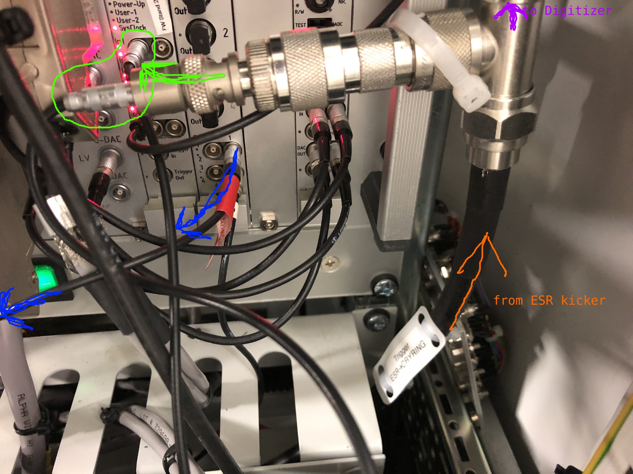 Figure: Injection kicker @ 2021 beamtime. Kicker trigger signal from the ESR kicker (orange). This signal is split via a t-piece: First, trigger signal to Digitizer (cyan). Second, trigger signal to kicker electronics (green). Output from kicker electronics to kicker hardware (blue).
The figure above shows the wiring of the CRYRING injection kicker. This kicker electronics is triggered via a hardware trigger signal generated by the ESR extraction kicker. This signal arrives in the kicker rack via a BNC cable (orange). Via t-piece the same signal is further distributed to a digitizer hosted in another rack in the CRYRING cave. This kicker has a hard synchronization to the ESR extraction kicker (RF signal)
Figure: Injection kicker @ 2021 beamtime. Kicker trigger signal from the ESR kicker (orange). This signal is split via a t-piece: First, trigger signal to Digitizer (cyan). Second, trigger signal to kicker electronics (green). Output from kicker electronics to kicker hardware (blue).
The figure above shows the wiring of the CRYRING injection kicker. This kicker electronics is triggered via a hardware trigger signal generated by the ESR extraction kicker. This signal arrives in the kicker rack via a BNC cable (orange). Via t-piece the same signal is further distributed to a digitizer hosted in another rack in the CRYRING cave. This kicker has a hard synchronization to the ESR extraction kicker (RF signal)
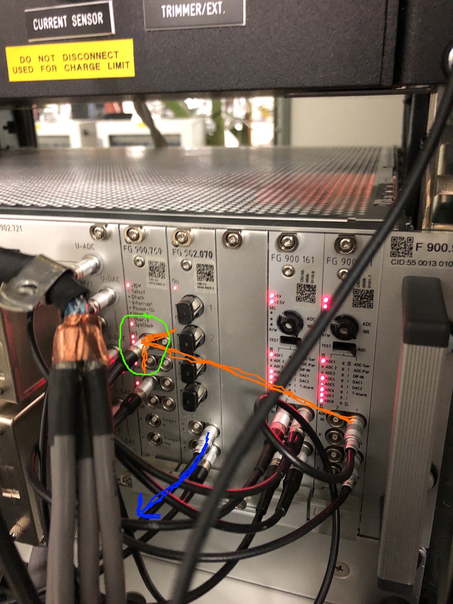 Figure: Extraction kicker @ 2021 beamtime. Additional I/O module for generation of kicker trigger signal (orange). Trigger input at kicker electronics (green). Output from kicker electronics to kicker hardware (blue).
The figure above shows the wiring of the CRYRING extraction kicker. This kicker electronics is triggered via a an internal trigger. Unlike the injection kicker, this kicker has no hard synchronization to an RF-signal.
Figure: Extraction kicker @ 2021 beamtime. Additional I/O module for generation of kicker trigger signal (orange). Trigger input at kicker electronics (green). Output from kicker electronics to kicker hardware (blue).
The figure above shows the wiring of the CRYRING extraction kicker. This kicker electronics is triggered via a an internal trigger. Unlike the injection kicker, this kicker has no hard synchronization to an RF-signal.
Beamtime 2022 with B2B System
The B2B has introduced the following changes.- kicker electronics is triggered by the b2b system (green input)
- b2b system has needs access to the output of the kicker electronics (blue output, T-piece)
- not implemented in 2022: access to the signal of the kicker magnet probe
- for both kickers triggering is done via simple Lemo cable inside the rack (PEXARIA output, LVTTL)
- for triggering the digitizer at the injection kicker there are two options
- option 1, reuse T-piece. Pro: straight forward. Con: Potential ground loops destroying Pexaria I/O as these are fast I/Os not pretected by opto-couplers
- option 2, there is no need for trigger cable from the kicker to the digitizer. Instead, the digitizer uses the timing messages CMD_B2B_TRIGGEREXT. Pro: no analog cables. Con: no easy rollback. Preferred option by the b2b team
Beamtime 2023
The main new feature is the implementation of access to the kicker magnet probe signal. Unlike SIS18 or ESR, 'spare' magnet probes have not been implemented. The only choice is to tap the probe signal to the digitizer. The main boundary condition is to get a signal but not to disturb the analog signal for the digitizer. After a few iterations with tries and errors, the following setup has been implemented.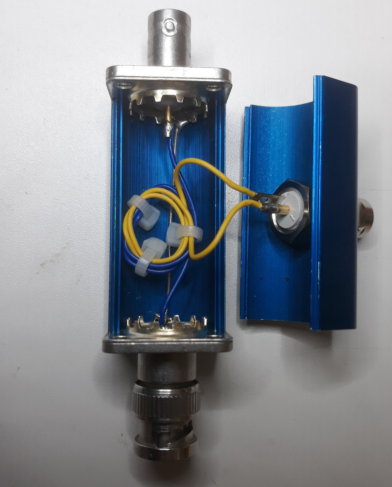 Figure: Air-cored coil with two windings as 'tap' for the magnet probe signal.
As shown in the figure above, the signal is tapped using an air-cored coil with two windings only. This tap is put in-line with the signal to the digitizer.
Figure: Air-cored coil with two windings as 'tap' for the magnet probe signal.
As shown in the figure above, the signal is tapped using an air-cored coil with two windings only. This tap is put in-line with the signal to the digitizer.
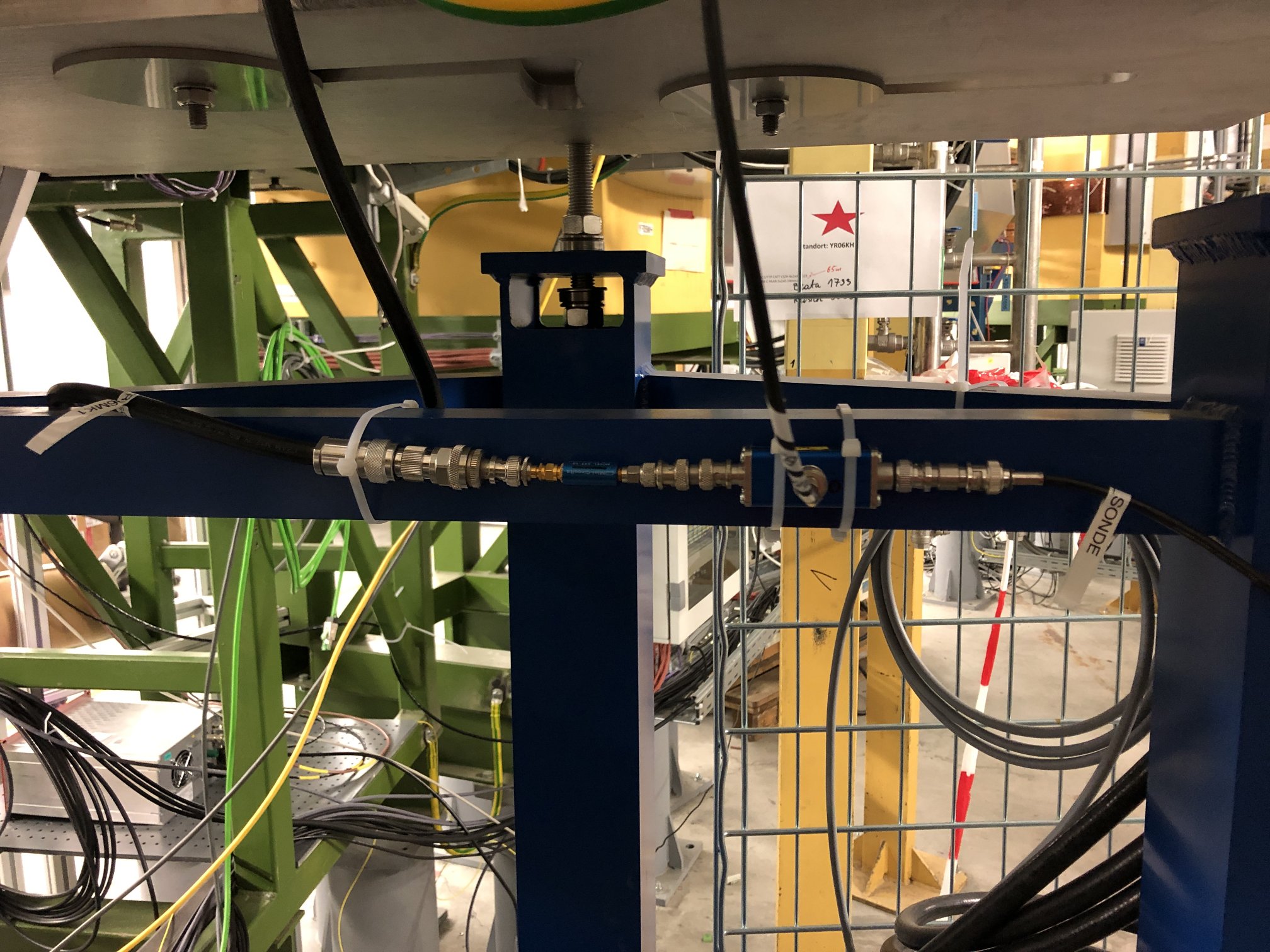 Figure: From right to left: signal from probe, 'tap', attenuator, signal to digitizer.
The signal from the tap is shown below.
Figure: From right to left: signal from probe, 'tap', attenuator, signal to digitizer.
The signal from the tap is shown below.
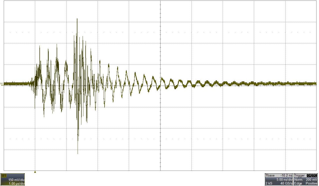 Figure: Signal from tap with extraction kicker at 7 mrad (about 8 kV).
The resulting signal available for the b2b system is very poor. Not only that the typical amplitude is only about 300 mV, but the remaining signal shape is just 'ringing'. As a consequence, the comparators developed for and used at SIS18 and ESR can not be used. A special solution has been implemented by our colleagues from the Experiment Electronics.
Figure: Signal from tap with extraction kicker at 7 mrad (about 8 kV).
The resulting signal available for the b2b system is very poor. Not only that the typical amplitude is only about 300 mV, but the remaining signal shape is just 'ringing'. As a consequence, the comparators developed for and used at SIS18 and ESR can not be used. A special solution has been implemented by our colleagues from the Experiment Electronics.
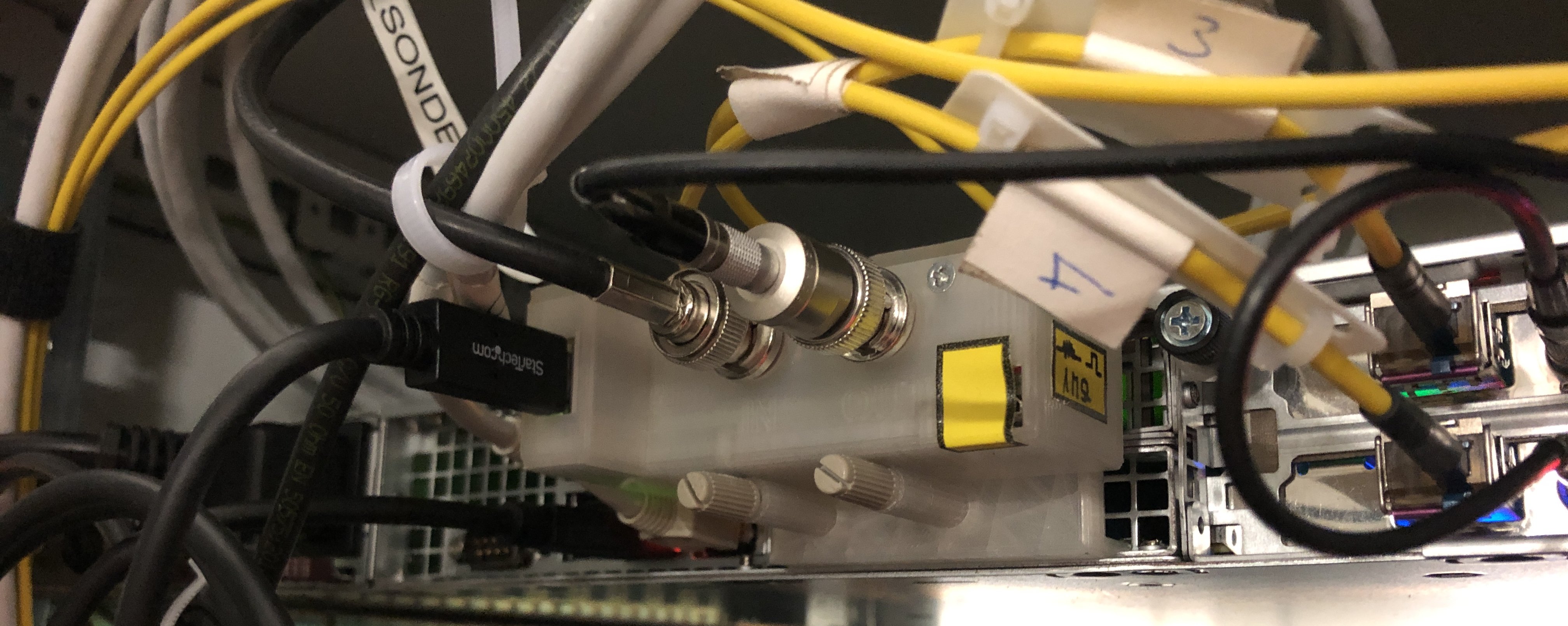 Figure: Installed prototype of a comparator dedicated for CRYRING kickers in a grey transparent box that is mounted at the backside of a 1U server.
The figure above shows the new comparator mounted the backside of a 1U server. Server and comparator are installed in the cabinet of the extraction kicker. The comparator receives power and settings data via USB from the server. The comparator delivers a clean LVTTL signal that is timestamped with a precision of 1 ns with one of the two PCIe timing receivers. The server uses an operating system provided via a standard ACO ramdisk to host dedicated software for the b2b system.
Figure: Installed prototype of a comparator dedicated for CRYRING kickers in a grey transparent box that is mounted at the backside of a 1U server.
The figure above shows the new comparator mounted the backside of a 1U server. Server and comparator are installed in the cabinet of the extraction kicker. The comparator receives power and settings data via USB from the server. The comparator delivers a clean LVTTL signal that is timestamped with a precision of 1 ns with one of the two PCIe timing receivers. The server uses an operating system provided via a standard ACO ramdisk to host dedicated software for the b2b system.
On-Site
vielleicht ein paar Bilder ... -- DietrichBeck - 23 June 2023

| I | Attachment | Action | Size | Date | Who | Comment |
|---|---|---|---|---|---|---|
| |
exctractionKicker-magnet-probe-tap-small.jpg | manage | 259 K | 23 Jun 2023 - 11:35 | DietrichBeck | air cored coil |
| |
extractionKicker_beamtime2021.JPG | manage | 568 K | 20 Jul 2021 - 14:19 | DietrichBeck | extraction kicker at 2021 |
| |
extractionKicker_comparatorInstallation.JPG | manage | 934 K | 23 Jun 2023 - 11:50 | DietrichBeck | comparator installation cryring extraction kicker |
| |
extractionKicker_probe-tap-overview-small.JPG | manage | 504 K | 23 Jun 2023 - 11:41 | DietrichBeck | extractionKicker tap overview |
| |
extractionKicker_signal-from-tap-small.jpg | manage | 131 K | 23 Jun 2023 - 12:02 | DietrichBeck | signal from tap at cryring extraction kicker |
| |
injectionKicker_beamtime2021.JPG | manage | 472 K | 20 Jul 2021 - 14:13 | DietrichBeck | injection kicker at 2021 |
Edit | Attach | Print version | History: r6 < r5 < r4 < r3 | Backlinks | View wiki text | Edit wiki text | More topic actions
Topic revision: r6 - 23 Jun 2023, DietrichBeck
- Toolbox
-
 Create New Topic
-
 Index
Index
-
 Search
-
 Changes
-
 Notifications
-
 RSS Feed
-
 Statistics
-
 Preferences
Ideas, requests, problems regarding Foswiki? Send feedback