|
|
You are here: Foswiki>BunchBucket Web>BunchBucketDocumentation>BunchBucketHowTo>BunchBucketHowB2BKickerTiming (03 Dec 2021, DietrichBeck)Edit Attach
How-To: Towards Complete Kicker Timing
Introduction
This page tries to summarize my knowledge (db, December 2021) on kicker timing at GSI. The focus is on hardware parameters.Set-Values
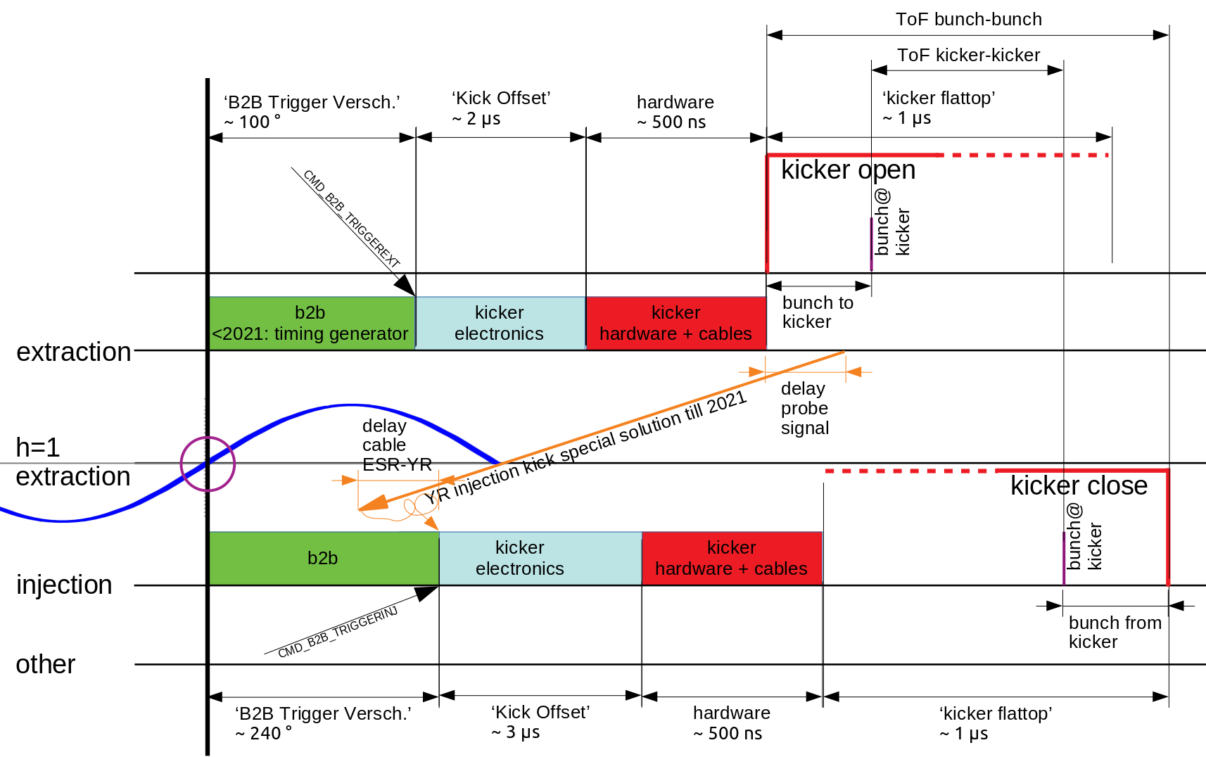 Figure: Components involved in kicker timing. Shown are configurable delays by the 'bunch-to-bucket' system (green) and the kicker electronics (light blue). Fixed hardware delays due to cables and electronic components are indicated in red. The length of the 'kicker flattop' is configurable too. The orange lines and measures indicate the so far special solution for triggering the CRYRING injektion kicker; here the signal of the actual kicker magnet probe is used as a trigger (there is a long cable from the ESR kicker room to rack YR injection kicker insdie the YR cave). The figure is not to scale. Details see text.
The figure above gives an overview on the kicker timing. Here, the b2b system replaces the so-called 'Timing Generators' that have been used up to the 2021 beam time. Please have a look at this overview.
The actual extraction process is aligned to a positive zero-crossing a the signal by the h=1 group DDS of the extraction ring. For timing the flat top of the kicker (= the kicker reaches its set-value), the following offsets and delays need to be considered.
Figure: Components involved in kicker timing. Shown are configurable delays by the 'bunch-to-bucket' system (green) and the kicker electronics (light blue). Fixed hardware delays due to cables and electronic components are indicated in red. The length of the 'kicker flattop' is configurable too. The orange lines and measures indicate the so far special solution for triggering the CRYRING injektion kicker; here the signal of the actual kicker magnet probe is used as a trigger (there is a long cable from the ESR kicker room to rack YR injection kicker insdie the YR cave). The figure is not to scale. Details see text.
The figure above gives an overview on the kicker timing. Here, the b2b system replaces the so-called 'Timing Generators' that have been used up to the 2021 beam time. Please have a look at this overview.
The actual extraction process is aligned to a positive zero-crossing a the signal by the h=1 group DDS of the extraction ring. For timing the flat top of the kicker (= the kicker reaches its set-value), the following offsets and delays need to be considered.
| hardware signal | unit | ParamModi Value | unit | description |
|---|---|---|---|---|
| trigger offset | ns | 'Kick Start', 'Trigger Verschiebung' | degree | the configurable hardware value is an offset of positive or negative sign; the ParamModi value is a positive delay only; the is very similar to the ParamModi value 'Kick Start' that acted on the 'Timing Generator' |
| kicker delay | ns | 'Kick Offset' | ns, us | configurable delay within kicker electronics |
| kicker hardware + cables | n/a | n/a | delay caused by electric components and cables of the kicker system [1] | |
| bunch to kicker | n/a | n/a | the rising edge of the kicker magnet should happen during the bunch-gap; it takes some time until the bunch itself reaches the kicker | |
| Time-of-Flight kicker/kicker | n/a | n/a | the time-of-flight of the extracted bunch from extraction to injection kicker | |
| Time-of-Flight bunch/bunch | n/a | n/a | the time-of-flight of the extracted bunch from the moment of the rising edge of the kicker magnet field (extraction) to the the falling edge of the kicker magnet field at injection. This might depend on a variety of boundary conditions such as the harmonic numbers and bunch/bucket numbers |
Get-Values
Some of the kicker values can be retrieved by various sources| signal | where | description |
|---|---|---|
| trigger offset | B2B Monitor | set-value and get-value, 'kick set trig' |
| kicker delay | B2B Monitor | get-value, 'kick offset' |
| kicker hardware + cables (extraction) | B2B Monitor | get-value, 'kick probeR'; rising edge of the probe signal at the extraction kicker; note: this value includes an additional delay (cable from kicker to kicker room) |
| kicker hardware + cables (injection) | B2B Monitor | get-value, 'kick prober'; edge of the probe signal at the injection kicker; note: this value includes an additional delay (cable from kicker to kicker room) |
| kicker flattop SIS18+ESR | PropHelper |


| I | Attachment | Action | Size | Date | Who | Comment |
|---|---|---|---|---|---|---|
| |
b2b-complete-kicker-timing.png | manage | 172 K | 03 Dec 2021 - 08:39 | DietrichBeck | complete kicker timing |
Edit | Attach | Print version | History: r4 < r3 < r2 < r1 | Backlinks | View wiki text | Edit wiki text | More topic actions
Topic revision: r4 - 03 Dec 2021, DietrichBeck
- Toolbox
-
 Create New Topic
-
 Index
Index
-
 Search
-
 Changes
-
 Notifications
-
 RSS Feed
-
 Statistics
-
 Preferences
Ideas, requests, problems regarding Foswiki? Send feedback