Concept B2B-Lite
This is an outdated document!
Table of Contents
Plan A - Reminder
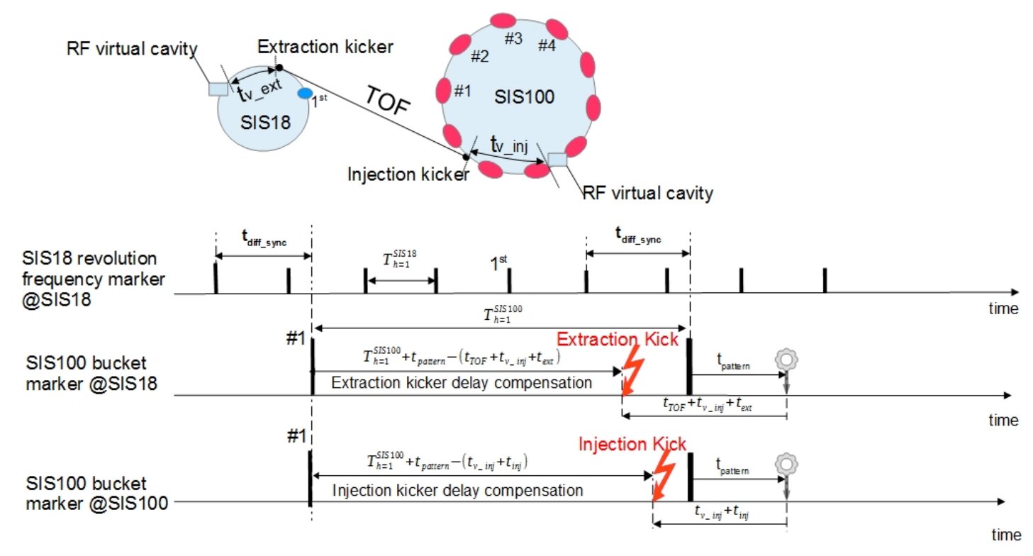 Figure:
 Sketch for B2B transfers from SIS18 to SIS100, figure from PhD Bai. Details see text.
A sketch for the B2B between two machines is shown in the above figure. The following tables describes some of the parameters.
| what |
description |
source |
comment |
| virtual cavity |
virtual position of RF signals |
N/A |
reference for RF signals, logic concept |
| tv_ext |
ToF from virtual cavity to kicker |
LSA |
extraction ring, depends on v/c |
| tv_inj |
ToF from virtual cavity to kicker |
LSA |
injection ring, depends on v/c |
| t
ext | kicker delay | LSA | extraction ring |inis
| tinj |
kicker delay |
LSA |
injection ring |
| tpattern |
delay for specific bucket pattern |
LSA |
same for extraction and injection ring |
| ToF |
Time-of-Flight between rings |
LSA |
depends on v/c |
| Th=1,ext |
revolution period of ring |
LSA |
extraction ring |
| Th=1,inj |
revolution period of ring |
LSA |
injection ring |
| EKDC |
extraction kicker delay compensation |
LSA |
EKDC = Th=1,inj + tpattern - (ToF + tv_inj + text) |
| IKDC |
injection kicker delay compensation |
LSA |
IKDC = Th=1,inj + tpattern - (tv_inj + tinj) |
Table: B2B parameters
Plan B - B2B-Lite
Definitions
Plan B is B2B without signal reproduction. Instead of reproducing the signal of the injection machine (SIS100) at the extraction machine (SIS18), the idea is to use the bucket label signal '1st' from the extraction machine (SIS18) directly and make use of the known time difference T
diff-sync from the virtual cavity of the extraction machine (SIS18) to the one at the injection machine (SIS100).
- the vaue of Tdiff-sync can be calculated from LSA settings
- a FTRN can timestamp digital signals to about 1 ns
- we assume the 1st (#1) at the group DDS of the extraction (injection) machine as digital 'TTL' signals
- we assume the actual frequency values can be read within the respective SCUs via Wishbone
- B2B can predict the synchronization windows sufficiently precise (better 1 us)
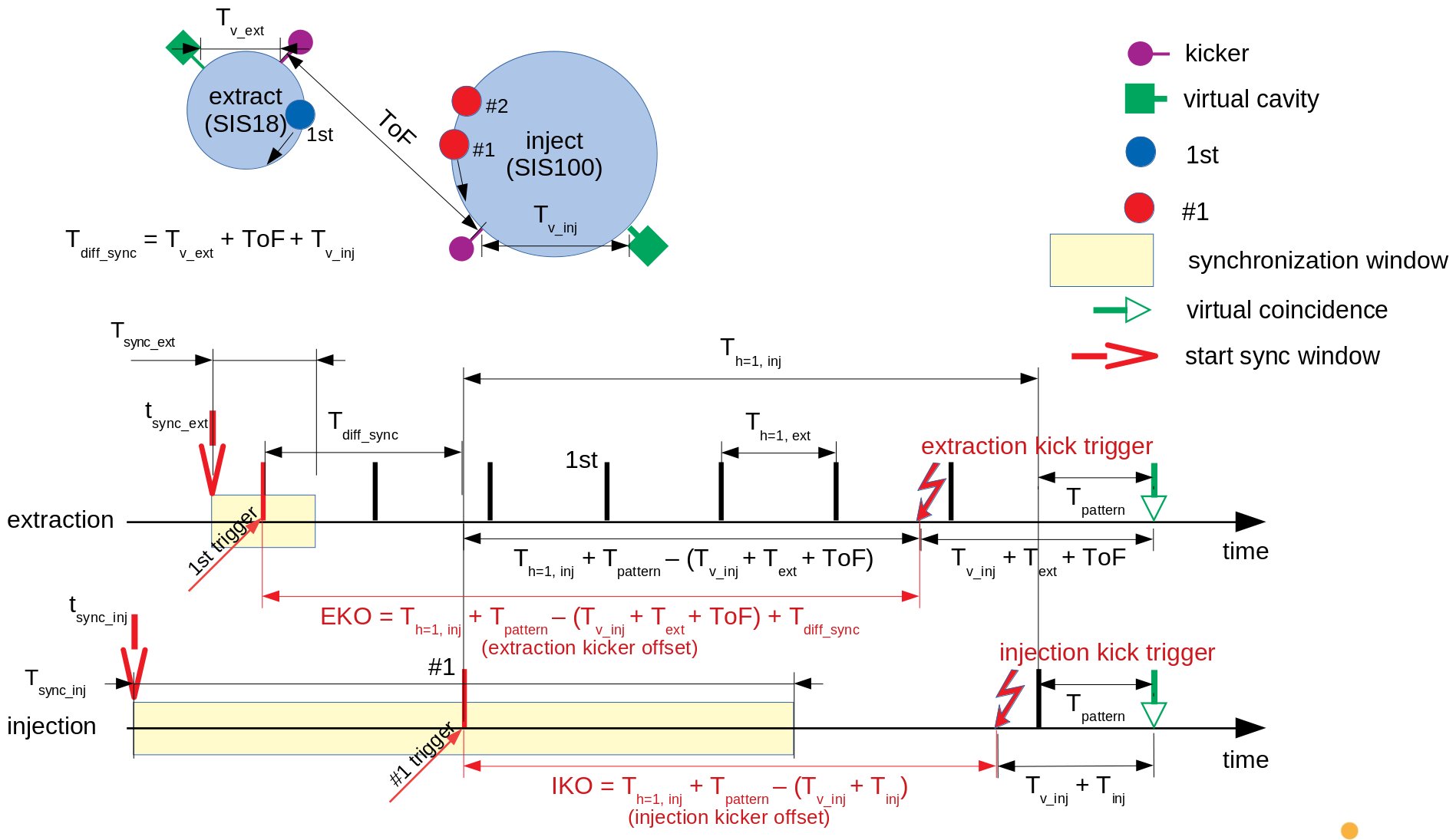 Figure:
 An idea for B2B without the need for
SIS100 bucket marker @SIS18 . Top: Sketch of transfer; shown are kicker positions (magenta marker with circle), virtual cavity positions (green marker with square), first bunches in ring (1st, #1). Bottom: Sketch of timing; shown are bunch label markers (1st, #1, vertical black/red lines), (virtual) coincidence of requested bucket pattern at the virtual cavity of the injection machine (green marker with open triangle), trigger signal for kicker electronics (red flashes), 'bunch label marker triggers' (1st, #1, vertical red lines), start time of synchronization windows (red marker with line arrow) and synchronization windows (yellow boxes). Upper cap 'T' marks time differences, whereas lower cap 't' marks timestamps More details see text.
The example depicted in the figure above shows timing scheme for transfer between two rings. Here, the example of a transfer from SIS18 (2nd harmonics) to SIS100 (10th harmonics) is given.
The above table of B2B parameters can be extended:
| what |
description |
source |
comment |
| Tdiff-sync |
difference of revolution frequency markers |
LSA |
tdiff-sync = tv_ext + ToF + tv_inj |
| Tact, h=1, ext |
revolution period of ring |
actual value in group DDS1 |
extraction ring |
| Tact, h=1, inj |
revolution period of ring |
actual value in group DDS1 |
injecting ring |
| TLSA, h=1, ext |
revolution period of ring |
LSA |
extraction ring |
| TLSA, h=1, inj |
revolution period of ring |
LSA |
injecting ring |
| sync-winext |
synchronization window |
Central B2B Unit |
input to 'Trigger Decision' module |
| sync-wininj |
synchronization window |
Central B2B Unit |
input to 'Trigger Decision' module |
| 1st trigger |
bucket label signal, extraction ring |
group DDS extraction ring |
input to 'Trigger Decision' module (identified by 'sync-winext') |
| #1 trigger |
bucket label signal, injection ring |
group DDS injection ring |
input to 'Trigger Decision' module (identified by 'sync-wininj') |
| EKO |
extraction kicker offset |
LSA |
EKO = TLSA, h=1, inj + Tpattern - (ToF + Tv_inj + Text) + Tdiff_sync |
| EKO = TLSA, h=1, inj + Tpattern - (ToF + Tv_inj + Text) + Tv_ext + ToF + Tv_inj |
| EKO = TLSA, h=1, inj + Tpattern + Tv_ext - Text |
| IKO |
injection kicker offset |
LSA |
IKO = TLSA, h=1, inj + Tpattern - Tv_inj - Tinj |
| tsync-ext |
start of sync-winext |
Central B2B Unit (CBU) |
|
| tsync-inj |
start of sync-wininj |
Central B2B Unit (CBU) |
|
| Tsync-ext |
length of sync-winext |
Central B2B Unit (CBU) |
|
| Tsync-inj |
length of sync-wininj |
Central B2B Unit (CBU) |
|
Table: More B2B parameters for 'plan B'.
1If control loops are frozen, the actual values of T
act, h=1 can be directly derived from LSA values (technical note by D. Lens).
Idea
The main idea for 'Plan B' is based on the following assumptions:
- The values of actual frequencies of the 1st harmonic are exactly determined
- by register values in the group DDS of the extraction and injection rings.
- by LSA values (beam phase control loops based on phase shift, not on frequency shift)
- The White Rabbit based timing system and group DDS input clock have a common reference clock.
- Once the phase difference between 1st harmonic group DDS's of the two rings is known for a specific (White Rabbit) timestamp, the evolution of the phase relationship into the future does
- not depend on the uncertainty of the frequencies (uncertainty is 0!)
- only depend on the uncertainty of the phase measurement at the specific (White Rabbit) timestamp
- As the frequencies are known, the phase difference at a specific time could be derived from the measurement of time difference of '0-crossings' of the two DDS signals.
- Frequency Beating only, no Phase Shift
As a working hypothesis, the timestamp of a '0-crossing' of the 1st harmonics could be done via the Timestamp Latch Unit (TLU) of a PCIe FTRN with a precision of 1ns. This requires the signal of the 1st harmonics is available as a 50 Ohm TTL output of the group-DDS.
Data Flow and Implementation
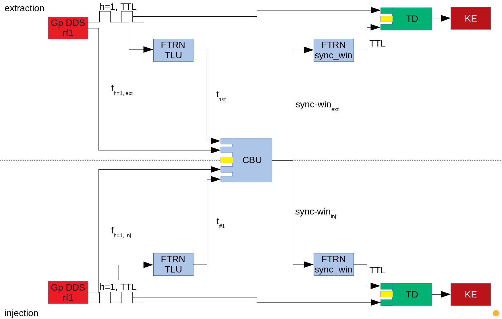 Figure:
 Data Flow. Show is RF equipment (red boxes), B2B equipment (blue boxes), trigger decision module (green boxes) and kicker electronics (brown boxes). Input from LSA is indicated by small yellow boxes. Details see text.
The figure above shows the hardware view of the data flow for B2B. Required hardware components are listed in the following table.
| what |
HW platform |
LSA input |
timing event |
new HW |
new HDL |
comment |
| group DDS's |
SCU crates |
X |
X |
|
? |
required: Wishbone access to actual h=1 frequency |
| ? |
? |
required: h=1 signal as rectangular TTL 50 Ohm |
| FTRN TLU |
FTRN with ns resolution |
|
X |
|
|
Pexaria, Exploder or SCU4 |
| FTRN sync-win |
FTRN with ns resolution |
|
X |
|
|
Pexaria, Exploder or SCU4, ns resolution only required for yet unforeseen requirements  |
| CBU |
lm32 program |
X |
X |
|
|
some lm32 in some FTRN, connection to WR network required |
| TD |
based on DIOB?, SCU crate |
X |
X |
X |
X |
requires development (HEL?), consider MPS requirements as well |
| KE |
? |
X |
X |
X |
X |
requires development (HEL?), consider MPS requirements as well |
Table: Overview on components for B2B-Lite. Columns
LSA input and
timing event indicate required input. Columns
new HW and
new HDL indicate developments that need to be done.
Procedure (Simplified)
The following procedure could be applied
- ...
- DM initiates transfer
- (RF control loops frozen; as control loops use phase-shifting algorithms, the h=1 frequencies are identical to LSA values, if the loops are frozen)
- (h=1 frequencies known to a Central B2B Unit (CBU), LSA values might be sufficient)
- ...
- simultaneous measurement of
- phase measurement of '1st harmonics 0-crossing' at extraction machine
- phase measurement of '1st harmonics 0-crossing' at injection machine
- transfer of the phase values to CBU
- CBU calculates
- time when the 1st harmonics of both machines are synchronized
- time for '1st trigger' (based on LSA values for Tdiff-sync, Tv_ext, Text), see remark (1)
- time for '#1 trigger' (based on LSA values for Tdiff-sync, Tv_inj, Tinj), see remark (1)
- tsync-ext = t1st trigger - Th=1, ext / 2, will be sent to TDM, see remark (1)
- tsync-inj = t#1 trigger - Th=1, inj / 2, will be sent to TDM, see remark (1)
- Tsync-ext = Th=1, ext, for diagnostic purposes
- Tsync-inj = Th=1, inj, for diagnostic purposes
- transfer of tsync-ext and Tsync-ext to a FTRNext close to the 'Trigger Decision Module' at the extraction machine
- transfer of tsync-inj and Tsync-inj to a FTRNinj close to the 'Trigger Decision Module' at the injection machine
- FTRNext generates sync-winext (required for Trigger Decision Module)
- FTRNinj generates sync-wininj (required for Trigger Decision Module)
- Group DDS's at extraction and injection machine generate 1st and #1 signals (required for Trigger Decision Module)
- 'Trigger Decision Modules' generate the signals 'injection kick trigger' and 'extraction kick trigger' required for kicker electroncis
- ...
Remark (1)
- it is planned, that the internal logic of the TDM is triggered based on a logical AND of the signals tsync-inj/ext from the CBU and h=1 sync from the DDS. In that case
- the values 'time 1st/#1 trigger' serve for diagnostics only
- the values tsync-inj/ext will be sent to the TDM
- as an alternative, the CBU could send the value 'time 1st/#1 trigger' directly, but with reduced precision. In this case
- the values 'time 1st/#1 trigger' will be sent to the TDM (which no longer requires the h=1 input from the DDS)
- the values tsync-inj/ext serve for diagnostics only
| origin |
destination |
gid |
evtno |
param |
comment |
| DM |
CBU |
EXT_B2B_INJ |
CMD_B2B_START |
N/A |
init transfer |
| CBU |
TR_TLU_EXT |
EXT_B2B_INJ |
CMD_B2B_PMEXT |
Th=1, ext |
init phase measurement at extraction machine; has period as parameter |
| CBU |
TR_TLU_INJ |
EXT_B2B_INJ |
CMD_B2B_PMINJ |
Th=1, inj |
init phase measurement at injection machine; has period as parameter |
| TR_TLU_EXT |
CBU |
EXT_B2B_INJ |
CMD_B2B_PREXT |
th=1, ext |
send result of phase measurement; has timestamp as parameter |
| TR_TLU_INJ |
CBU |
EXT_B2B_INJ |
CMD_B2B_PRINJ |
th=1, inj |
send result of phase measurement; has timestamp as parameter |
| CBU |
TR_SYNC_EXT |
EXT_B2B_INJ |
CMD_B2B_SYNCEXT |
N/A |
schedule extraction sync trigger, tbd |
| CBU |
TR_SYNC_INJ |
EXT_B2B_INJ |
CMD_B2B_SYNCINJ |
N/A |
schedule injection sync trigger, tbd |
| CBU |
diagnostic |
EXT_B2B_INJ |
CMD_B2B_DIAGMATCH |
N/A |
diagnostic info, indicates when phases match |
| CBU |
diagnostic |
EXT_B2B_INJ |
CMD_B2B_DIAGEXT |
N/A |
diagnostic info, projects measured phase into the future (useful for calibration) |
| CBU |
diagnostic |
EXT_B2B_INJ |
CMD_B2B_DIAGINJ |
N/A |
diagnostic info, projects measured phase into the future (useful for calibration) |
| CBU |
KICKER_EXT |
EXT_B2B_INJ |
CMD_B2B_KICKEXT |
N/A |
experimental: trigger for kicker |
| CBU |
KICKER_INJ |
EXT_B2B_INJ |
CMD_B2B_KCIKINJ |
N/A |
experimental: trigger for kicker |
| ... |
... |
EXT_B2B_INJ |
... |
diagnostic data |
send diagnostic data (to be discussed) |
DEPRECATED Table: Timing messages. As a first idea, a transfer from SIS18 -> SIS100 would use a dedicated timing group SIS18_B2B_SIS100.
Proposal for GID and EvtNo
GID
| GID (d) |
GID (x) |
Name |
Description |
Source |
| |
0x12c |
SIS18_RING |
(exists: CMD_B2B_TRIGGER... are sent here) |
SIS18 CBU |
| |
0x154 |
ESR_RING |
(exists: CMD_B2B_TRIGGER... are sent here) |
ESR CBU |
| |
0x0d2 |
CRYRING_RING |
(exists: CMD_B2B_TRIGGER... are sent here) |
CRYRING CBU |
| |
0x136 |
SIS100_RING |
(exists: CMD_B2B_TRIGGER... are sent here) |
SIS100 CBU |
| 0d928 |
0x3a0 |
SIS18_B2B_EXTRACT |
B2B internal: extraction from SIS18 |
SIS18 CBU |
| 0d929 |
0x3a1 |
SIS18_B2B_ESR |
B2B internal: transfer SIS18 to ESR |
SIS18 CBU |
| 0d930 |
0x3a2 |
SIS18_B2B_SIS100 |
B2B internal: transfer SIS18 to SIS100 |
SIS18 CBU |
| 0d931 |
0x3a3 |
SIS18_B2B_PP |
B2B internal: transfer SIS18 to plasma physics (after discussing with S. Goette, I think this is not required) |
SIS18 CBU |
| 0d933 |
0x3a5 |
ESR_B2B_EXTRACT |
B2B internal: extraction from ESR |
ESR CBU |
| 0d934 |
0x3a6 |
ESR_B2B_CRYRING |
B2B internal: transfer ESR to CRYRING |
ESR CBU |
| 0d938 |
0x3aa |
CRYRING_B2B_EXTRACT |
B2B internal: extraction from CRYRING |
CRYRING CBU |
| 0d944 |
0x3b0 |
SIS100_B2B_EXTRACT |
B2B internal: extraction from SIS100 |
SIS100 CBU |
| ... |
... |
... |
... |
|
Table: Group numbers used for internal communication by the B2B system.
The table above is not complete and needs to be extended for upcoming machines like CR, HESR using the following scheme:
- < ring A >_B2B_< ring b >: transfer between rings
- < ring A >_B2B_PP: transfer from a ring to PHELIX; (special case, requires synchronizing with laser instead of RF)
- < ring A >_B2B_EXTRACT: extraction from a ring; the target is unspecified and might be an experiment (FRS, PRIOR ...)
EvtNo
| !EvtNo (d) |
!EvtNo (x) |
Name |
Description |
| 0d2048 |
0x800 |
CMD_B2B_PMEXT |
B2B internal: request phase measurement (extraction) |
| 0d2049 |
0x801 |
CMD_B2B_PMINJ |
B2B internal: request phase measurement (injection) |
| 0d2050 |
0x802 |
CMD_B2B_PREXT |
B2B internal: send result of phase measurement (extraction) |
| 0d2051 |
0x803 |
CMD_B2B_PRINJ |
B2B internal: send result of phase measurement (injection) |
| 0d2052 |
0x804 |
CMD_B2B_TRIGGEREXT |
B2B internal: trigger kicker electronics (extraction) [1] |
| 0d2053 |
0x805 |
CMD_B2B_TRIGGERINJ |
B2B internal: trigger kicker electronics (injection) [1] |
| 0d2054 |
0x806 |
CMD_B2B_DIAGMATCH |
B2B internal: optional diagnostic, indicates when phases match |
| 0d2055 |
0x807 |
CMD_B2B_DIAGEXT |
B2B internal: optional diagnostic (extraction) |
| 0d2056 |
0x808 |
CMD_B2B_DIAGINJ |
B2B internal: optional diagnostic (injection) |
| 0d2057 |
0x809 |
CMD_B2B_DIAGKICKEXT |
B2B internal: optional kick diagnostic (extraction) |
| 0d2058 |
0x80a |
CMD_B2B_DIAGKICKINJ |
B2B internal: optional kick diagnostic (injection) |
| ... |
... |
... |
... |
| 0d2079 |
0x81f |
CMD_B2B_... |
reserved til here |
Table: Event numbers used for internal communication of the B2B system. Only 0x800..0x805 are used for operation. Other event numbers serve for optional run-time diagnostics.
[1] CMD_B2B_TRIGGER.... will be sent to the relevant group. Example: CMD_B2B_TRIGGEREXT is sent to SIS18_RING when the extraction kicker shall be triggered.
Phase Matching Algorithm
Due to White Rabbit, timing receivers share a common notion of time. Hence, it is easy to solve phase matching in the time domain. In addition, the lm32 soft-cores don't support floating point calculations and adding numbers is match faster compared to (emulated) divisions. In order to minimize uncertainties due to rounding of numbers, the algorithm described here uses a timescale in atoseconds.
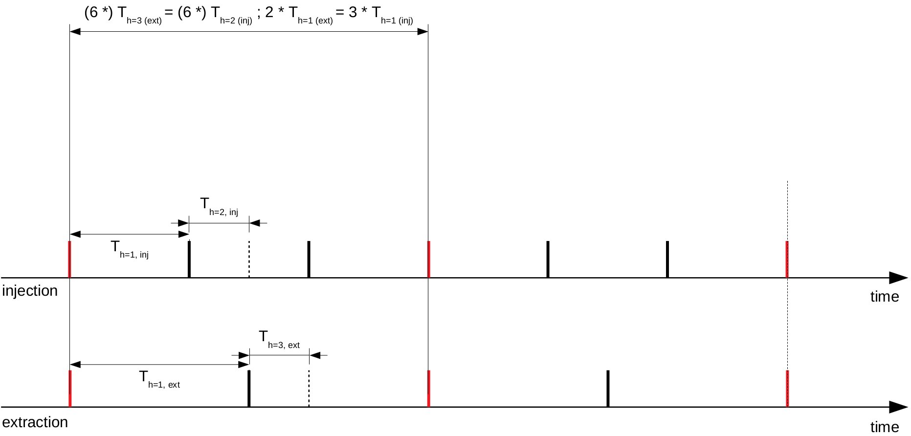 Figure:
 Shown are markers of h=1 rf-periods for extraction (bottom) and injection (top). The ratio of the rf-periods is 2/3. The h=1 signals match after 2 (3) periods for extraction (injection), markers for a 'match' are shown in red. The lowest combination of harmonic numbers to achieve this situation is h=3 (extraction) and h=2 (injection), see dashed markers.
The figure above shows a situation with two ring machines using (from a operations points of view) a weird rf-ratio of 2/3; there is no beating and the h=1 signals are perfectly matched for the lowest common multiple of frequencies. In this case the periods match when using h=3 for extraction and h=2 for injection. As can be seen in the figure above, the h=1 signals match after 2 * 'h=1 periods' for extraction and 3 * 'h=1 periods' for injection.
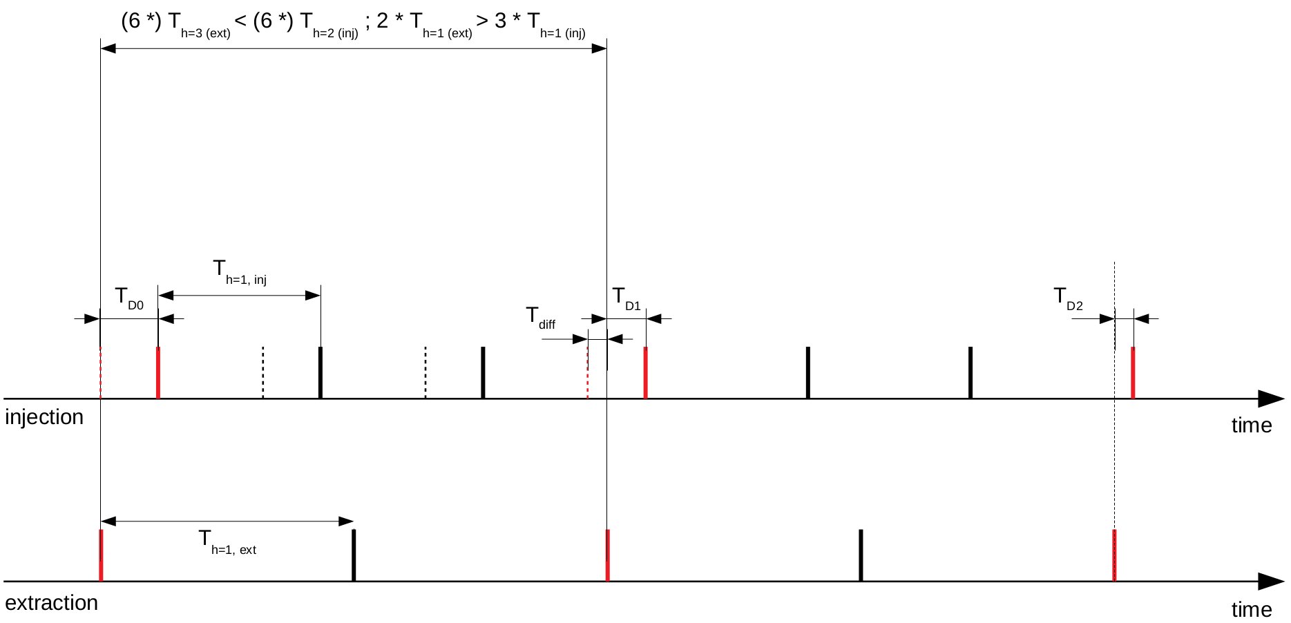 Figure:
 This is the same figure with a slight detuning of frequency to achieve beating. Shown is a situation, where the h=1 frequency of the injection machine is increased slightly. Dashed markers indicate how the red markers of the injection machine evolves compared to the extraction machine. After one iteration, the time difference between red markers is T
diff. Beating can be observed by the time differences (T
D0..D2) between the (almost) matching solid red markers, which becomes smaller witch each iteration.
The figure above shows a situation for frequency beats. From the point of view of the extraction machine, the red marker of the injection machine 'comes closer' with every iteration. One just has to wait until the red marker of the injection machine matches/passes the one of the extraction machine. This is predictable. T
diff is known from LSA values and T
D0 is the time difference between the phase measurements at the two machines, see remark (2). The ratio T
D0 / T
diff is just the number of iterations until phase matching of the h=1 signals will be achieved; the length of one iteration is known too.
Remark (2)
- the algorithm has to distinct between two cases, depending which machine is detuned in which direction
- for practical reasons, the starting conditions of the algorithm has to be chosen such, that TD0 is smaller than the shortest h=1 period. This can easily be achieved by shifting the measured phase values by their periods
- the algorithm implies
- rf beam control loops are frozen prior to the start of the phase matching procedure
- rf beam control loops for stabilization are based on a phase shifting method; in this case the rf frequencies are identical to LSA values
Documents
--
DietrichBeck - 30 Jan 2020


 Create New Topic
 Index
Index
 Search
 Changes
 Notifications
 RSS Feed
 Statistics
 Preferences