You are here: Foswiki>Applications Web>LsaMainPage>LsaFrequentlyAskedQuestions (13 Apr 2020, JuttaFitzek)Edit Attach
Q: What is LSA?
LSA (LHC Software Architecture)
LSA is a set of business logic and applications used for setting generation and management. It is a software product from CERN. It is highly database driven and has one data model for all accelerators. Since LSA is a modular framework, that is easily adaptable, it is planned to use it as core component for settings management. For covering the needs of a full beam- and settings management system, there is additional functionality needed, which are not or not yet covered by LSA as it is now. These aspects are investigated at the moment by B/BEL and F/FSY. The following description is taken from “LHC Era Core Controls Application Software” written by Mike Lamont and Lionel Mestre, CERN and extended with additional information related to GSI . To support the clear understanding of concepts, examples were taken from GSI rather then from CERN, also the system overview was adapted to how it is planned to use LSA at GSI.Introduction
The LSA project team came into being in 2001 at CERN following the realignment of the application software development activity after the merging of the PS and SL division to form the AB (now BE/CO) department. It started with the idea that much of the functionality for accelerator control is common across machines and the clear aim was to develop tools that could be easily re-used and extended for the controls of several accelerators.In 2003 they started to work on a new architecture that could be extended to support the controls of the upcoming LHC.
Architecture principles
Figure 1 gives the complete LSA software stack. We describe here the main principles. The main principles are:Distributed
The distributed nature is build-in in the design. Using a lightweight container, the architecture was made of 3 logical tiers that can be deployed in 2 or 3 physical tiers. Designing APIs that can be deployed remotely bring constraints that have to be dealt with, such as limiting the number of round trips between the remote client and the server and limiting the amount of data transferred each time. Those constraints were taken into account in the API defined.Modular
The LSA core is split in modules with a clear definition and a clear API. Each module provides a coherent set of functionality. The goal was to maximize reuse of modules and to enforce proper separation of concerns between modules.Layered
Each layer from top (GUI) to bottom (Persistence – Equipment) is isolated from the other. The client layer is designed to be remote and is interacting with the other layers through a unique façade. Choice of technology in one layer does not affect the layer above. For instance, all equipment access is performed through JAPC (Java API for Parameter Control), regardless of whether it is using JMS (Java Messaging System) transport or CMW (CERN middleware for equipment access).Database access is encapsulated inside Data Access Objects (DAO). One DAO can use different technology depending on the situation (CERN used Hibernate but switched to direct JDBC access through the Spring Framework).
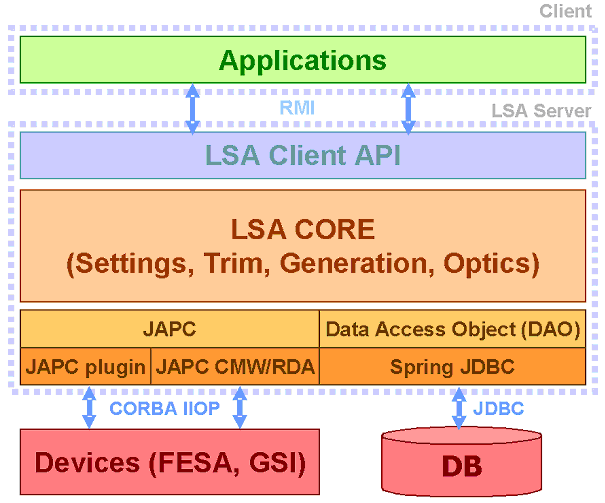 Figure: The LSA software stack
Main concepts
The LSA core software is based on few important underlying concepts.Parameter
Parameters in LSA describe something for which a value shall be assigned, calculated or measured. Most important characteristics of a parameter are its name and its value's format (the latter is defined in the parameter's type).- Parameters are named using the notation "<device>/<property[#field]>".
- A parameter has a type that defines some characteristics shared across all parameters of that type.
- Actually existing, addressable equipment such as a power converter
- Actually existing, but non-addressable equipment such as a magnet
- A "virtual device" such as the beam. The virtual "beam device" typically has properties such as the vertical or horizontal tune, chromaticity, etc.
- A parameter describing a physical value ("virtual")
- The parameter named "SIS18BEAM/QH" which describes the beam's horizontal tune in SIS18's ring section
- A parameter describing an intermediate calculation result (also "virtual")
- The parameter "GS11MU2/I" which references the SIS18 GS11MU2 dipole's current as a function over time
- A parameter referencing a device's property ("non-virtual")
- The parameter named "GS11MU2/RAMPVALS" which describes the device front-end's property and it's specific technical data format
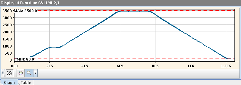 Figure: SIS18 GS11MU2 dipole's current as a function over time
More information:
LSA Training Course part 1: parameter hierarchy and makerules, page 4
Parameter hierarchy
Parameters are organized in a parameter model that describes the relations between parameters. The parameter model is an oriented graph of parameters. The roots of that graph are the top level parameters (physics parameters such as horizontal tune, chromaticity, etc...). Those root parameters have dependent ones (such as magnet strengths, magnet currents). The leaves of the graph are the hardware parameters (such as the current in the power converters). The position of a parameter within the hierarchy is defined by- it's source parameters, i.e. the parameters it is calculated from
- it's dependent parameters, i.e. the parameters which need it's value for their own calculation
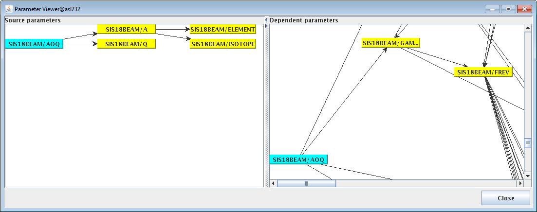 Figure: Position of the parameter "SIS18BEAM/AOQ" (mass to charge ratio) within the currently used SIS18 parameter hierarchy.
On the "source parameter" side on the left, it can be seen that "SIS18BEAM/AOQ" is calculated using "SIS18BEAM/A" (atomic mass) and "SIS18BEAM/Q" (charge). "SIS18BEAM/A" is in turn determined by the information which element and isotope is concerned.
"SIS18BEAM/AOQ" is a direct input in the calculation of four other parameters, as one can determine by the number of arrows running from it's representation on the right hand "dependent parameters" view. One of those is visible in the screenshot, "SIS18BEAM/GAMMA", which represents the relativistic gamma factor. Apart from direct dependents, the hierarchy graph in ParamModi also shows all indirect dependencies down to the leaf nodes.
More information:
Progress and Challenges during the Development of the Settings Management System for FAIR, page 2
Context
A context represents a period of time during which a parameter can be associated with a value. We distinguish five types of contexts with different characteristics- Beam Process
- Cycle
- Super cycle
- Beam Production Chain
- Pattern
Beam process (used by both CERN and GSI)
A beam process defines a specific procedure (injection, ramp, extraction…) that happens in a defined section of an accelerator or transfer line (e.g. SIS18RING, SIS18_TE_ES).
Beam processes are executed as atomic operations within the control system; once started, a beam process is always executed to its end.
There is a distinction between beam-in beam processes, which define the state of the machine with beam, and beam-out beamprocesses, which define the state of the machine when there is no beam.
Beam Process Types are used to define certain characteristics that all beam processes of this type share.
Cycle (used at CERN and at GSI until SIS18 beam time 2016)
It defines a beam (from injection to extraction) including the beam-out part. Cycles are usually organized in supercycles because they do not necessarily preserve the state of the machine. The state of the machine at the end of the cycle is not necessarily the same as the one at the start because, for example, of possible remnant effects in the magnets. A special type of cycles is the standalone cycle which doesn't need a supercycle as a container.
Super Cycle (used at CERN)
Defines a series of Cycles used to produce beams for known clients. The main characteristic of the Super Cycle is that it can be repeated in a cycling machine. The state of the machine at the start of the Super Cycle is the same as the state at the end of the Super Cycle.
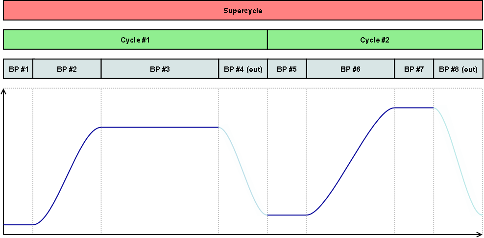 Figure: Eight beam processes scheduled in two cycles scheduled in a super cycle
Beam Production Chain (used at GSI)
A Beam Production Chain describes the the whole lifespan of a beam from its initial creation at the source until it is destroyed at the target or dump. Unlike the Cycle or the SuperCycle, a Beam Production Chain can span accross multiple accelerators (e.g. first linear accelerator, then ring accelerator, then storage ring). The intention of this way of scheduling is to make a complex facility easier to manage for operators and maximize machine utilization / parallelization of beam production.Pattern (used at GSI)
Comparable to what the Super Cycle is for its Cycles, the Pattern is used to define which Beam Production Chains will be executed within the facility during the time in which the Pattern is active. While there is one pattern that is executed many times or indefinately (until its execution is stopped), there can optionally be alternative patterns which get executed on request (e.g. when a certain an experiment is supplied with beam on request).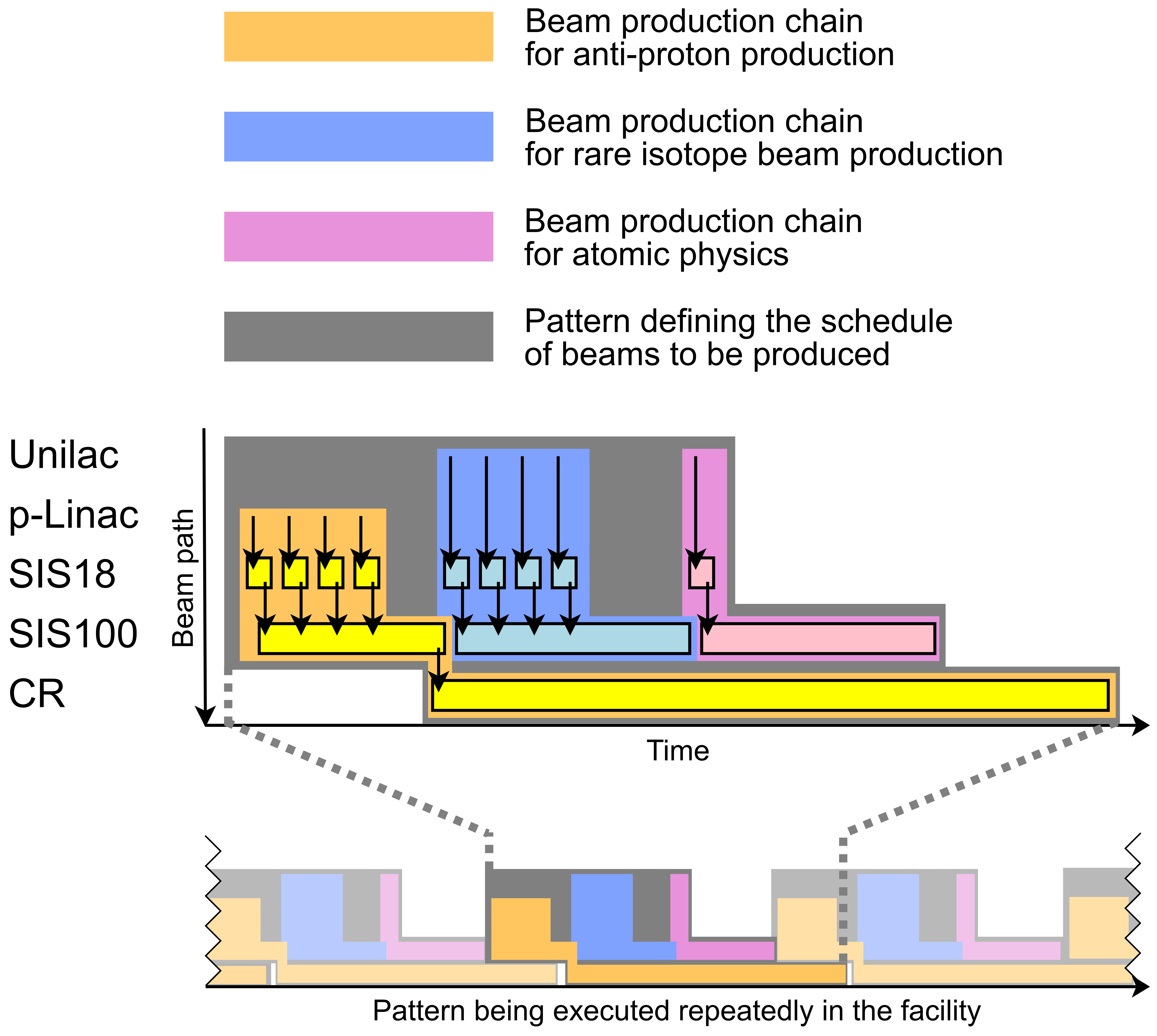 Figure: Example for parallel beam operation showing scheduling of beam production chains into patterns. HESR accumulating the anti-protons is omitted.
Setting
A setting represents the value of a parameter for a given context.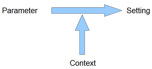 Figure: Relation between parameter, context and setting
That setting's value is made up of two parts: the target and the correction. The target part is usually what has been generated. It is the theoretical value. The correction part is the empiric part that results from all modifications (trims) applied during operation to the value in order to establish the correct beam characteristics.
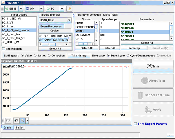 Figure: Visualization of a settingShown is the current in a SIS18 power converter during the ramp
When a trim is performed on a given setting (on a value for a given parameter at a given beam process) the requisite changes are propagated to the settings of the dependent parameters. At the level of the trim the correction value is updated while the modification is propagated to the target value of the dependents. There is an extensive API to manipulate settings. Applications like ParamModi utilize that API to modify and visualize the settings.
Rules
Rules define how a modification on a setting affects other related settings. We have three types of rules to cover the three types of relations between settings.Makerule
It is the recipe that translates from the setting of one parameter to the settings of its dependent parameters. The make rule is defined for a relation between two parameter types. For instance if we trim a physics parameter (like QH), one make rule will describe how to compute the strength in the different dependent magnets based on the change done in QH’s setting.Incorporation rule
Describes how a change on a setting is incorporated into the next or the previous setting in the supercycle. If a trim on a setting is changing at least one end point, the change has to be propagated to the adjacent settings and the incorporation rule describes how this should be. The incorporation rules are used for example to incorporate a change done at a given point in time into the rest of the setting done (moving also other parts of the function, smoothing out the change etc). This feature is used for instance at CERN for trimming the orbit correctors for the orbit steering.Linkrule
These rules are used to compute the setting of a parameter during the beam out beamprocesses. Linkrules are defined per hardware type of the device the parameter belongs to. As physics parameters do not have settings during the beam-out beamprocess, it is nevertheless necessary to generate settings for all hardware parameters, e.g. to ramp down the magnets.Trim
A trim is a change on one or several setting(s). Trimming settings of physics parameters is the preferred way to adapt the generated settings to the specific conditions of a given accelerator, hardware parameters are typically derived from the settings of physics parameters. Trims are archived and it is possible to revert them to come back to a previous situation. Once a trim is performed at a given level, the trim is propagated to the dependent parameter settings and all the changed hardware settings are automatically sent to the hardware when appropriate.LSA core modules
Each module of LSA core is a separate software project that can be built and released independent of each other. The modules provide the services to handle settings, contexts, rules and trims.Optics module
The Optics module manages all configuration data. This includes the layout of the accelerator or transfer line, the twiss, the different optics etc. There are applications to visualize the data from the Optics. The optics module also defines knobs. A knob is a scalable parameter which has several dependent parameters. A typical knob example is a local bump: the bump amplitude in millimeters is translated into strength values for several correctors. The strength values needed to perform the bump are optics dependent. The machine model is used to calculate for a given optic the values of the dependent parameters for one unit of the knob. These values are assumed to vary linearly with the knob amplitude.Settings module
The Settings module handles the persistence and retrieval of all settings, parameters and trims. Settings can be modified and each modification is stored in a trim.The Settings Module also handles the different contexts. It has key functionality to access settings grouped by cycle or supercycle as settings are stored per beamprocess. Therefore, to obtain the setting of a cycle we potentially have to put together several settings of several beam processes.
Trim module
The Trim module provides the functionality to change the value of a setting of a given parameter and to propagate the changes to the settings of the dependent parameters. It defines the different rules used for that propagation. The trim module is the key module that provides the most complex functionality of the system.Generation module
The Generation module is an offline module used to create new supercycles and to generate the associated settings for all parameters. It makes use of the four other modules. Before any generation of a new super cycle can start, all parameters have to be defined in the database. For instance, for the TI8 and TT40 tests at CERN, both lines had to be defined carefully, with all power converters, all calibration curves, maximum and minimum currents for each power converter, optics, measurement devices etc. For some parameters (chromaticity sextupoles, main bends, quads and RF) there are also some configuration data to be set up, often depending on the type of particle and type of ramp to be used.Exploitation module
The Exploitation module is the gateway to the hardware. It handles all accesses and provides the necessary adaptation from a generic virtual device accepting settings to a specific one having different properties and constraints. The module also provides operation friendly hardware commands that can be executed from the middle tier and that are used from the equipment state application.Client module
All applications based on LSA use this API to communicate with the LSA core, i.e. the Client module is the façade for all clients to the middle tier. It provides the glue between the API offered to the clients and the API of the modules below. It offers a level of indirection that allow us to have great flexible in the API definition of the modules without impacting the client applications. This module also defines the boundary between local and remote interface. The entire client API is written with remote access in mind while everything behind is supposed to be collocated. This has a great impact on the way the APIs are defined.LSA integration, technical aspects
LSA is highly data driven, and relies on that data. In order to use LSA as central part of the beam- and settings management component, it is necessary to provide all needed data, which includes:- structure of the accelerators, transfer lines
- devices, properties together with their value types, limits..; calibration curves
- optics
- timing
All information has to be imported into the system with a good data quality (preferable automatisms and checks) and it has to be held up to date (e.g. triggers, scripts).
A correct and reliable data basis is vital for the LSA system to be able to perform its tasks. -- RaphaelMueller - 17 Dec 2009
| I | Attachment | Action | Size | Date | Who | Comment |
|---|---|---|---|---|---|---|
| |
BPCs_and_Patterns_v2_fully_transparent.png | manage | 422 K | 15 Apr 2016 - 15:19 | HannoHuether | |
| |
Beam_process_cycle_super_cycle_scheduling.png | manage | 34 K | 15 Apr 2016 - 14:57 | HannoHuether | |
| |
GS11MU2-I-ParamModi.png | manage | 12 K | 15 Apr 2016 - 12:40 | HannoHuether | |
| |
Pattern_with_chains_example.png | manage | 59 K | 24 Jul 2015 - 13:44 | HannoHuether | |
| |
SIS18BEAM-AOQ-ParamModi.png | manage | 17 K | 15 Apr 2016 - 13:42 | HannoHuether | |
| |
relation_parameter_context_setting.png | manage | 11 K | 15 Apr 2016 - 15:47 | HannoHuether |
Edit | Attach | Print version | History: r8 < r7 < r6 < r5 | Backlinks | View wiki text | Edit wiki text | More topic actions
Topic revision: r8 - 13 Apr 2020, JuttaFitzek
 Copyright © by the contributing authors. All material on this collaboration platform is the property of the contributing authors.
 Ideas, requests, problems regarding Foswiki? Send feedback


