|
|
You are here: Foswiki>Timing Web>TimingSystemDocumentation>TimingSystemHowTo>TimingSystemHowOperateClockMaster (23 Dec 2017, DietrichBeck)Edit Attach
Clock Master: How-To Operate
- Clock Master: How-To Operate
- Introduction
- Background: Start here
- Background: WRS as Grandmaster Clock
- How-To: Check the Grandmaster Clock (including BuTiS)
- How-To: Restart the Grandmaster Clock
- How-To: Check Selection of GPSDO (WR and BuTiS)
- How-To: Resync the Grandmaster Clock using NTP
- How-To: Change of WRS Grandmaster Clock or Change of GPSDO
- How-To: Check Positioning of GPSDO PPS Pulse
- How-To: Fix Positioning of GPSDO Square Wave Outputs.
- How-To: Check the Grandmaster Clock and BuTiS c2 Clock
- Further Information
Introduction
This How-To is intended for the members of the timing team. The clock master is the White Rabbit Grandmaster Clock of the timing system. This How-To is a start and written from my (DB) perspective. For understanding the setup, please check the clock master doc first.Background: Start here
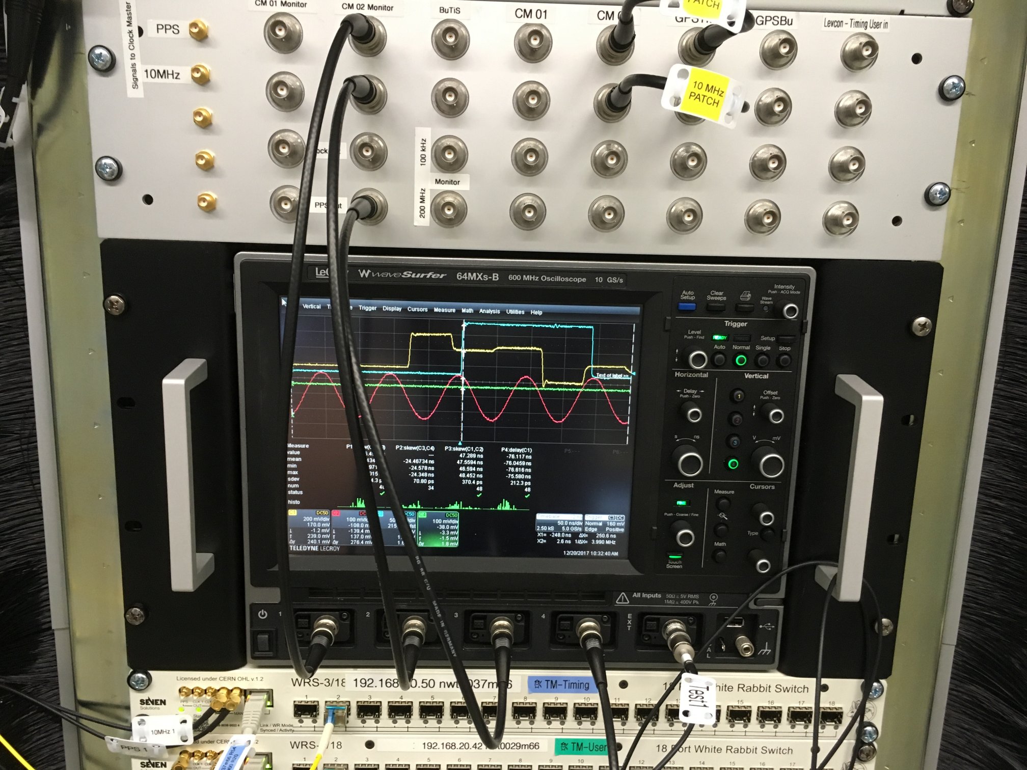 Figure: Normal view of patch panel and scope.
The figure above shows the starting point for most things.
Figure: Normal view of patch panel and scope.
The figure above shows the starting point for most things. - Ch1 connects to the PPS signal that is delivered to the clock master (via directional coupler)
- Ch2 connects to the 10 MHz signal that is delivered to the clock master (via directional coupler)
- Ch3 connects to the WR PPS signal from the clock master
- Ch4 is not connected.
- Ext Trigger is ignored here
- Ch1-3 maintain their connection / config for all of the following tasks.
- Ch1
- The PPS signal to the WRS has quite some jitter of up to 1ns. The GPSDO delivers this signal only as derived signal from its 10 MHz reference clock. This is normal and nothing to worry about.
- The PPS signal looks ugly. This is due to reflections. The reason is that the PPS input of the WRS has no 50 Ohm termination. It was a design decision by the people building the switch to have high-Z inputs only, as this allows using the switch with signal sources that can't provide sufficient current. This is nothing to worry about. Only the first rising edge is important.
- Ch2. The 10 MHz signal is a sine signal. Sine signals are much cleaner as they are less vulnerable to distortions or reflections and they require less bandwidth than square signals (a perfect square signal would require unlimited bandwidth).
Background: WRS as Grandmaster Clock
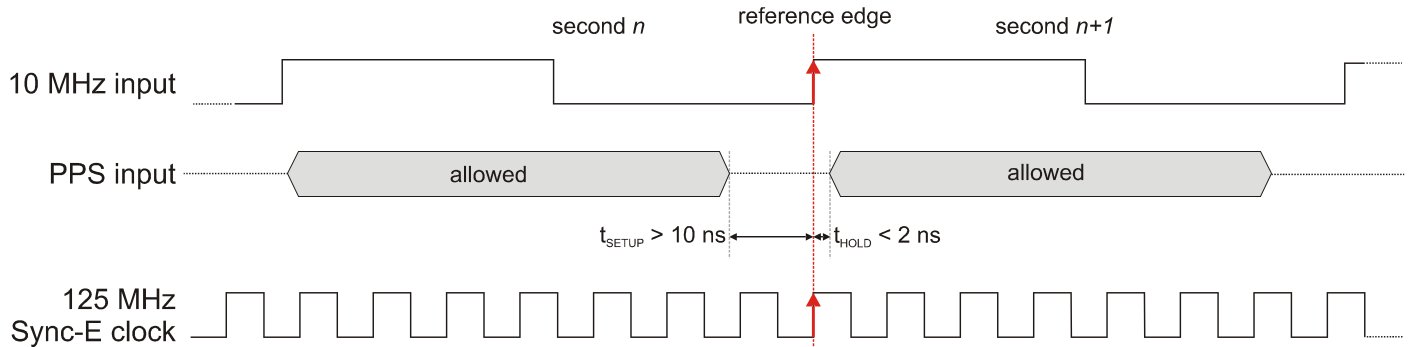 Figure: Alignment of clock edges at a WR Switch used as Grandmaster. Figure taken from here.
The Grandmaster Clock (WR Switch) uses the PPS signal from GPDSO basically an "announcement" of the full second: After the PPS signal is received, the WRS uses the next rising edge of the 10 MHz reference clock as "full second". By this, the 10 MHz clock and PPS signals are used to produce a the phase aligned White Rabbit 125MHz clock that is distributed in the White Rabbit network. In other words: The PPS signal from the GPSDO is used to ensure the alignment of the edges of both clocks at inter-second boundary which is the 10 MHz rising edge after the rising edge of the PPS pulse (see figure above). Typically, we apply a "negative delay" at the PPS signal produced at the GPSDO, such that the PPS signal of White Rabbit (at the output of a WR Switch or a WR node) is aligned to the "true PPS" signal. When setting things up, one should first verify the relationship of PPS vs 10 MHz in order to make sure that the switch transfers the PPS signal between two clock domains with no metastablity.
Hints for configuring a WR switch as grandmaster
Figure: Alignment of clock edges at a WR Switch used as Grandmaster. Figure taken from here.
The Grandmaster Clock (WR Switch) uses the PPS signal from GPDSO basically an "announcement" of the full second: After the PPS signal is received, the WRS uses the next rising edge of the 10 MHz reference clock as "full second". By this, the 10 MHz clock and PPS signals are used to produce a the phase aligned White Rabbit 125MHz clock that is distributed in the White Rabbit network. In other words: The PPS signal from the GPSDO is used to ensure the alignment of the edges of both clocks at inter-second boundary which is the 10 MHz rising edge after the rising edge of the PPS pulse (see figure above). Typically, we apply a "negative delay" at the PPS signal produced at the GPSDO, such that the PPS signal of White Rabbit (at the output of a WR Switch or a WR node) is aligned to the "true PPS" signal. When setting things up, one should first verify the relationship of PPS vs 10 MHz in order to make sure that the switch transfers the PPS signal between two clock domains with no metastablity.
Hints for configuring a WR switch as grandmaster
How-To: Check the Grandmaster Clock (including BuTiS)
Clock Synchronization and Alignment
The scope can be used for this.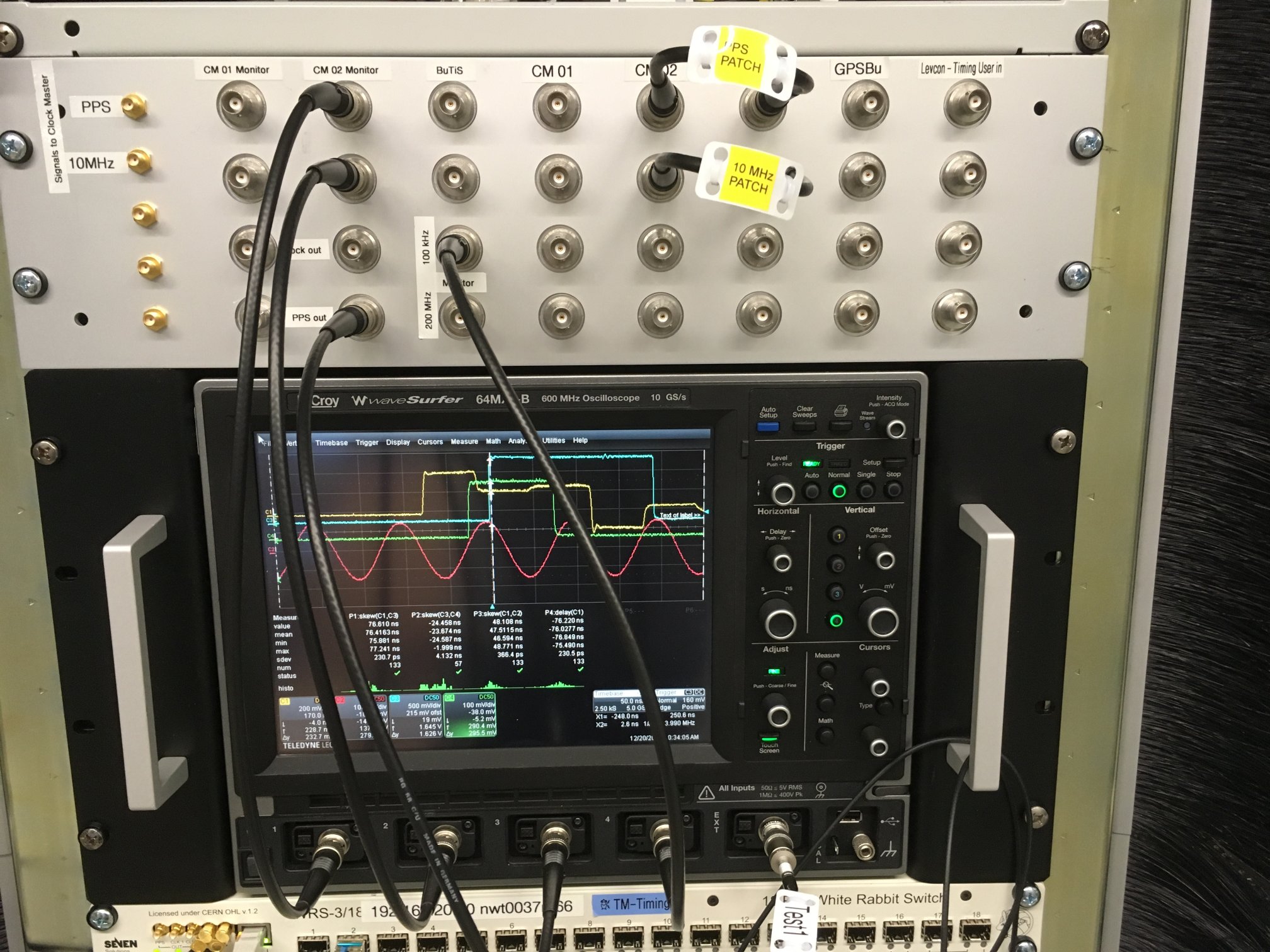 Figure: Checking the Clock Master on a scope (including BuTiS).
The figure above illustrates how to check the clock master on a scope.
Figure: Checking the Clock Master on a scope (including BuTiS).
The figure above illustrates how to check the clock master on a scope. - Ch1: WRS PPS input
- Ch2: WRS 10 MHz input
- Ch3: WRS PPS output (= WR PPS)
- WRS PPS input (yellow) and PPS output (cyan) are both visible and they don't move with respect to each other
- WRS PPS output (cyan) does not move with respect to the 10 MHz input (red).
- Problems? Need to restart the grandmaster clock to lock again (see below)
- CH4: BuTiS 100 kHz "T0" signal (green). Watch for WRS PPS output (cyan) and T0 signal (green). WR and BuTiS are locked to each other, if the following conditions are fulfilled
- both signals are visible
- both signals don't move with respect to each other
- the rising edges of both signals align with a precision of 5ns or better.
- Problems?
- check the selection of GPSDO (see below).
- improving missing or bad alignment needs to be done by the BuTiS people.
Correct TAI Time
First Method The management interface of the clock master is used for this. Logon as root. Do the following a few times.- type
wr_date get, but don't typereturnto execute the command yet - observe the TAI time displayed at frontpanel of the GPSDO.
- at a full minute (or full 10 seconds or whatever) hit
returnat the ssh windows to executewr_date get. After a bit of training, you'll manage to hit the full second with a precision much better than 100ms. - Compare the TAI time at the WRS with the time displayed at the WRS. Both should agree to better than 100ms. Problems? Resynch the clock master WRS system time with NTP (see below)
- Compare TAI and UTC time for correct UTC offset. Problems? You probably need to update the file
/usr/etc/leap-seconds.listat the switch.
- logon to SCU
-
eb-mon -ls dev/wbm0, make sure WR link is up and SCU is in track phase -
eb-mon -o dev/wbm0, the obtained value should be the current UTC offset to TAI.- UTC offset should be correct to better than one second. Offset is 37s @ 2017. Problems? Resynch the clock master WRS system time with NTP (see below)
- UTC offset should be correct with a precision of 10-20ms. Problems? Check a few other SCUs. If the obtained values are consistently off, check the positioning of the GPSDO PPS pulse (see below).
How-To: Restart the Grandmaster Clock
Warning: Following this recipe is not recommended during operation of the facility! A successful restart of the clock master requires the following- 10 MHz clock from GPSDO. Rising edge at the full second (no offset)
- PPS clock from GPSDO. Rising edge at the (full second - 50ns offset)
- /usr/etc/leap-seconds.list in the WRS is up to date
- NTP server is available (config in dot-conf of WRS)
- Logon to the clock master switch.
- Execute
reboot. Wait. - Watch the scope (use Ch1 as trigger source) and the LEDs at the WRS
- the PPS output signal from the WRS (Ch3, cyan signal) disappears.
- the WRS LED turn all black, then there is some kind of light show
- the PPS output signal (Ch3) re-appears. It moves a bit around with respect to the PPS from the GPSDO. Then it locks, this should happen after about 10-30 seconds.
- the WRS LED (link, activity) come back again.
- that status LED (2nd LED from left on front panel turns green)
- Check that the WRS is locked
How-To: Check Selection of GPSDO (WR and BuTiS)
Synchronization between White Rabbit and BuTiS requires both system to use the physical same GPSDO as reference clock. Check selection of the GPSDO for the timing system (BuTiS) by verifying the patch cables at the panel in rack 54 (rack 52).How-To: Resync the Grandmaster Clock using NTP
It may happen that the clock master locks successfully to the GPSDO, but it turns out that TAI and UTC are both off by the same amount. In such a case, the synchronization to NTP during the boot phase might have failed. In such a case, simply try rebooting the switch again. If that helps, fine. If not, try the following.- check system time (UTC) and WR time (TAI) via
wr_date get - while (UTC and TAI are not correct)
-
ntpd -q -p < ip number of NTP server > -
wr_date set host - check system time (UTC) and WR time (TAI) via ...
-
How-To: Change of WRS Grandmaster Clock or Change of GPSDO
Warning: Following this recipe requires stopping the operation of the facility!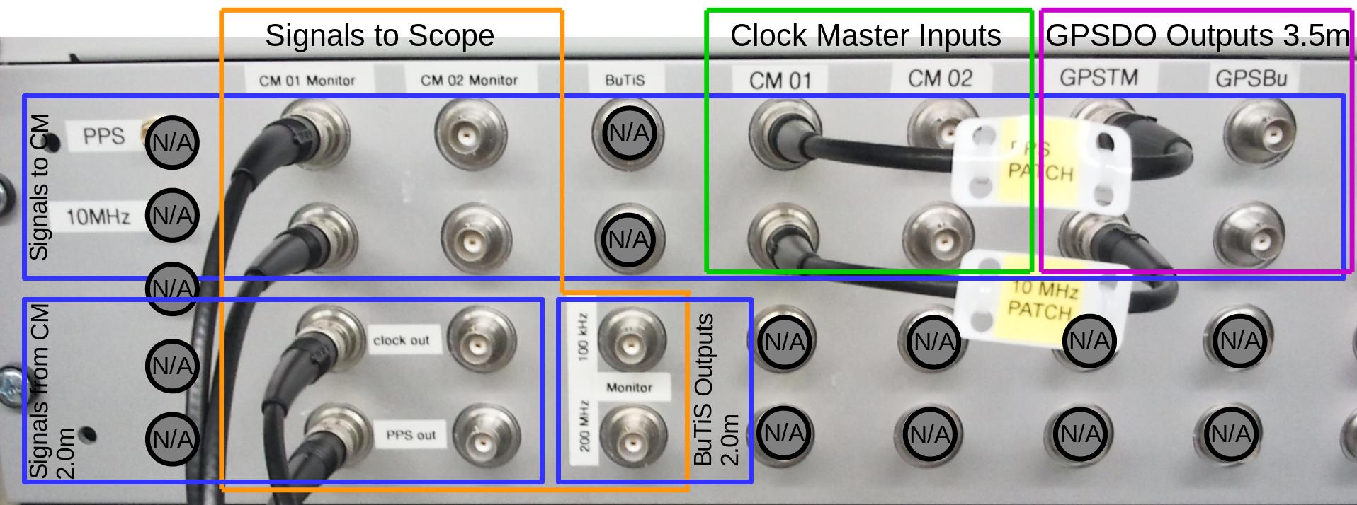 Figure: Patch panel for the clock master in rack 54.
In case of failure of the WR Grandmaster clock or GPSDO a switch-over to the backup system is required.
Figure: Patch panel for the clock master in rack 54.
In case of failure of the WR Grandmaster clock or GPSDO a switch-over to the backup system is required. - the operation in the facility must be stopped. It is required to follow the necessary procedures (main control room ...)
- to be on the safe side, prevent further operation by bringing the data master into a safe state.
- abort any activities that might still be resident
- kill FESA
- disconnect from the timing network (sometimes I am paranoid)
- if applicable: Change of Grandmaster clock
- change patch cables (yellow tag, see figure above) at the patch panel in rack 54
- no change required for BuTiS
- change of GPSDO
- change patch cables (yellow tag, see figure above) at the patch panel in rack 54
- BuTiS people need to change patch cables at panel in rack 52
- restart the Grandmaster clock (see above)
- check the Grandmaster clock (see above)
- check the synchronization with BuTiS (see above)
- things are fine? if yes, connect and bring up the data master again, a power cycle is probably easiest.
- verify correct operation of the timing system via the usual procedures
- things are fine? if yes, the operation in the facility may be continued following the necessary procedures.
How-To: Check Positioning of GPSDO PPS Pulse
The time scale distributed via WR PTP shall be correct and agree to "true" TAI better than one microsecond. As the PPS signal is a derived signal at the square wave outputs of the GPSDO, this implies correct configuration of those outputs. However, it has been observed a couple of times that the positioning of the PPS pulse obtained from the GPSDO is still not correct (mistake by user? bug? to be investigated ...). Watch out for the following warning signs.- at a SCU,
eb-mon -o dev/wbm0yields a value that differs from the full second by more than 20ms - in case you resynched the switch using
wr_date set, there is a warning that PPS differs by a significant value from the full second. - observing the scope using Ch3 as trigger source.
- Ch2 (10 MHz input to the WRS, red) and Ch3 (PPS output from the WRS, cyan) are obviously locked
- Ch1 (PPS input to the WRS, yellow) "has disappeared"
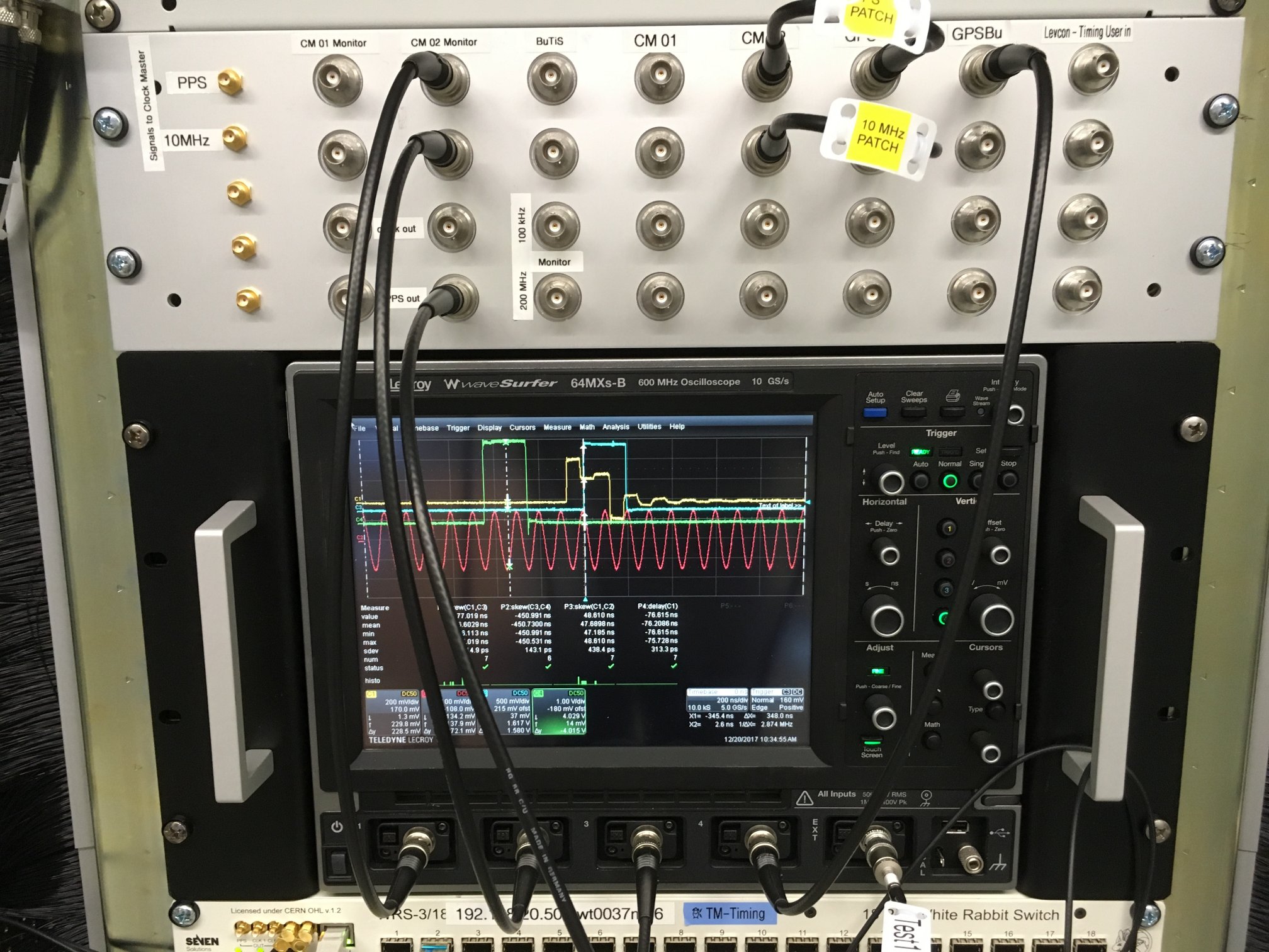 Figure: Comparing PPS pulses delivered by the GPSDO systems. Here GPDSO in rack 54 (rack 52) is active (backup).
The figure above illustrates how to check the alignment of GPSDO pulses.
Figure: Comparing PPS pulses delivered by the GPSDO systems. Here GPDSO in rack 54 (rack 52) is active (backup).
The figure above illustrates how to check the alignment of GPSDO pulses. - Ch1: WRS PPS input from active GPSDO (via coupler)
- Ch4: PPS signal from backup GPSDO (directly)
- measure the skew between the rising edges of both signals
- remember: oscillators can be either stable or precise. Our GPSDO devices have been designed for low phase noise / jitter. As a downside, the absolute positioning of the PPS signals is not very precise and may differ from the true value by up to 100ns.
- when comparing the PPS signals from the two distinct devices, a skew of up to several hundreds of nanoseconds is not uncommon. This is not an issue. However, the skew shall be smaller than 1 microsecond.
How-To: Fix Positioning of GPSDO Square Wave Outputs.
Warning: Following this recipe is not recommended during operation of the facility!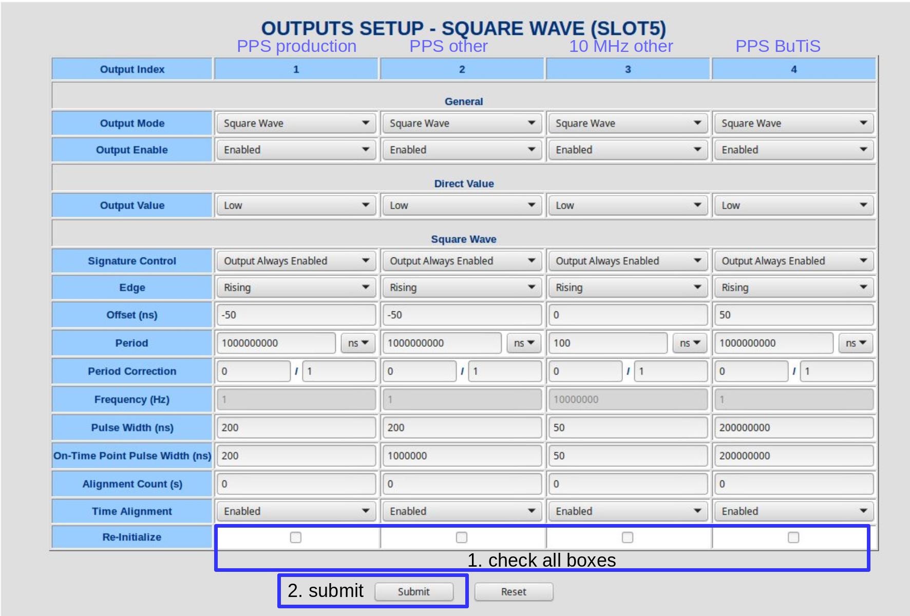 Figure: Fixing positioning of square wave pulses at the GPSDO.
In case square wave output signals of the GPSDO are suspected to be misaligned, try to follow the directions in the figure above.
Figure: Fixing positioning of square wave pulses at the GPSDO.
In case square wave output signals of the GPSDO are suspected to be misaligned, try to follow the directions in the figure above.
How-To: Check the Grandmaster Clock and BuTiS c2 Clock
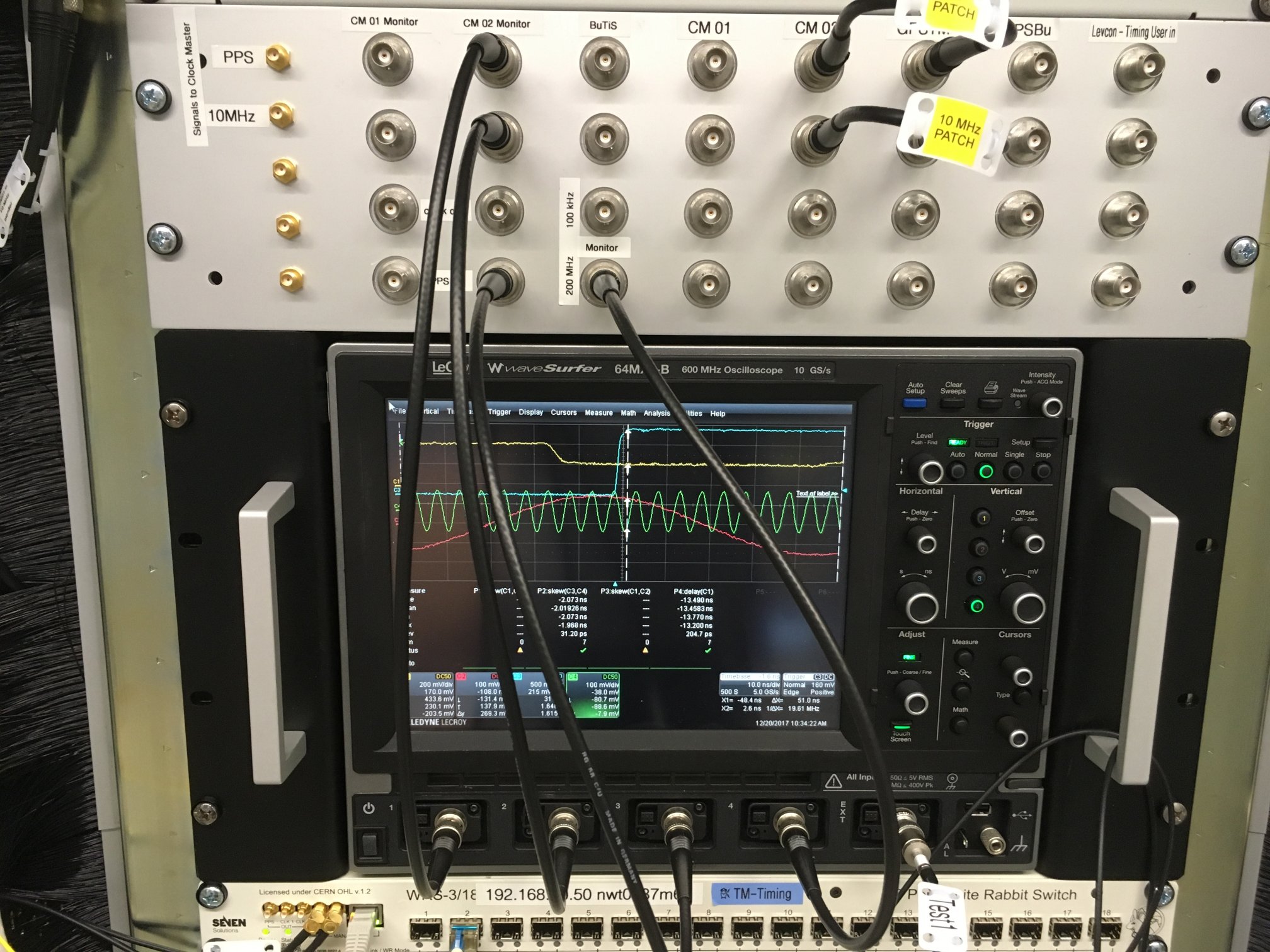 Figure: Checking the Grandmaster versus the BuTiS c2 clock.
The figure above depicts checking the Grandmaster versus the BuTiS c2 clock. This might be useful in cases when the T0 clock is not operational or detuned for specific purposes of the RF system.
Figure: Checking the Grandmaster versus the BuTiS c2 clock.
The figure above depicts checking the Grandmaster versus the BuTiS c2 clock. This might be useful in cases when the T0 clock is not operational or detuned for specific purposes of the RF system. - Ch3: WRS PPS output
- CH4: BuTiS 200 MHz "c2" clock. WR and BuTiS are locked to each other, if the following conditions are fulfilled
- both signals are visible
- both signals don't move with respect to each other
- Problems?
- check the selection of GPSDO (see below).
- improving missing or bad alignment needs to be done by the BuTiS people.
Further Information
- Note on using a WR Switch in grandmaster mode
- WR Switch developer manual
- Personal view on how-to use a switch


| I | Attachment | Action | Size | Date | Who | Comment |
|---|---|---|---|---|---|---|
| |
clockMasterView-butisC2.JPG | manage | 470 K | 22 Dec 2017 - 16:18 | DietrichBeck | check clock master and <nop>BuTiS c2 |
| |
clockMasterView-butisT0.JPG | manage | 472 K | 22 Dec 2017 - 12:53 | DietrichBeck | check clock master and <nop>BuTiS T0 |
| |
clockMasterView-normal.JPG | manage | 488 K | 22 Dec 2017 - 11:08 | DietrichBeck | normal clock master view |
| |
clockMasterView-ppsGpsdo.JPG | manage | 470 K | 22 Dec 2017 - 15:16 | DietrichBeck | check alignment of GPSDO PPS pulse |
| |
clockmaster-patch.jpg | manage | 186 K | 22 Dec 2017 - 16:29 | DietrichBeck | clock master patch panel |
| |
gpsdo_config.jpg | manage | 231 K | 22 Dec 2017 - 15:52 | DietrichBeck | GSPDO config of square wave outputs |
| |
grandMasterWRS.jpg | manage | 43 K | 03 Apr 2014 - 13:57 | DietrichBeck | reference clock inputs for a WR Switch |
Edit | Attach | Print version | History: r4 < r3 < r2 < r1 | Backlinks | View wiki text | Edit wiki text | More topic actions
Topic revision: r4 - 23 Dec 2017, DietrichBeck
Ideas, requests, problems regarding Foswiki? Send feedback