|
|
You are here: Foswiki>Timing Web>TimingSystemDocumentation>TimingSystemDocuments>TimingSystemDocumentsMaster>TimingSystemClockMaster (29 Oct 2019, DietrichBeck)Edit Attach
Clock Master Production
This page documents the configuration of the Clock Master. Please note the corresponding How To.Introduction
The Clock Master is the source of clock and time in the Timing System. The following components are involved.Overview
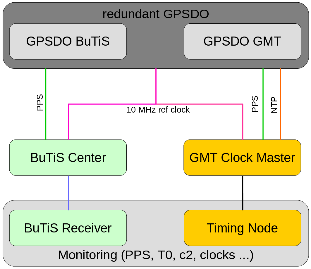 Figure: Reference clock distribution. Description see text.
The figure shows a simplified scheme for locking the BuTiS center as well as the Clock Master of the GMT to each other. A redundant GPSDO setup system provides a 10 MHz reference clock (pink) from the same signal source. The GPSDO also provides PPS signals (green) required by the GMT Clock Master and and BuTiS centre. The GMT Clock Master obtains the current time via NTP (orange). The ButiS (WR) networks are indicated in blue (black).
The prime feature of the GPSDO is to provide a stable reference clock from an internal stabilized oscillator. The link to the GPS system just provides long term stability.
A monitoring setup is connected to a BuTiS receiver station and the GMT. Its task is to confirm that BuTiS and GMT are successfully locked to each other. The monitoring setup includes an oscilloscope and other electronics.
Figure: Reference clock distribution. Description see text.
The figure shows a simplified scheme for locking the BuTiS center as well as the Clock Master of the GMT to each other. A redundant GPSDO setup system provides a 10 MHz reference clock (pink) from the same signal source. The GPSDO also provides PPS signals (green) required by the GMT Clock Master and and BuTiS centre. The GMT Clock Master obtains the current time via NTP (orange). The ButiS (WR) networks are indicated in blue (black).
The prime feature of the GPSDO is to provide a stable reference clock from an internal stabilized oscillator. The link to the GPS system just provides long term stability.
A monitoring setup is connected to a BuTiS receiver station and the GMT. Its task is to confirm that BuTiS and GMT are successfully locked to each other. The monitoring setup includes an oscilloscope and other electronics.
Time
See here.Cable Plan
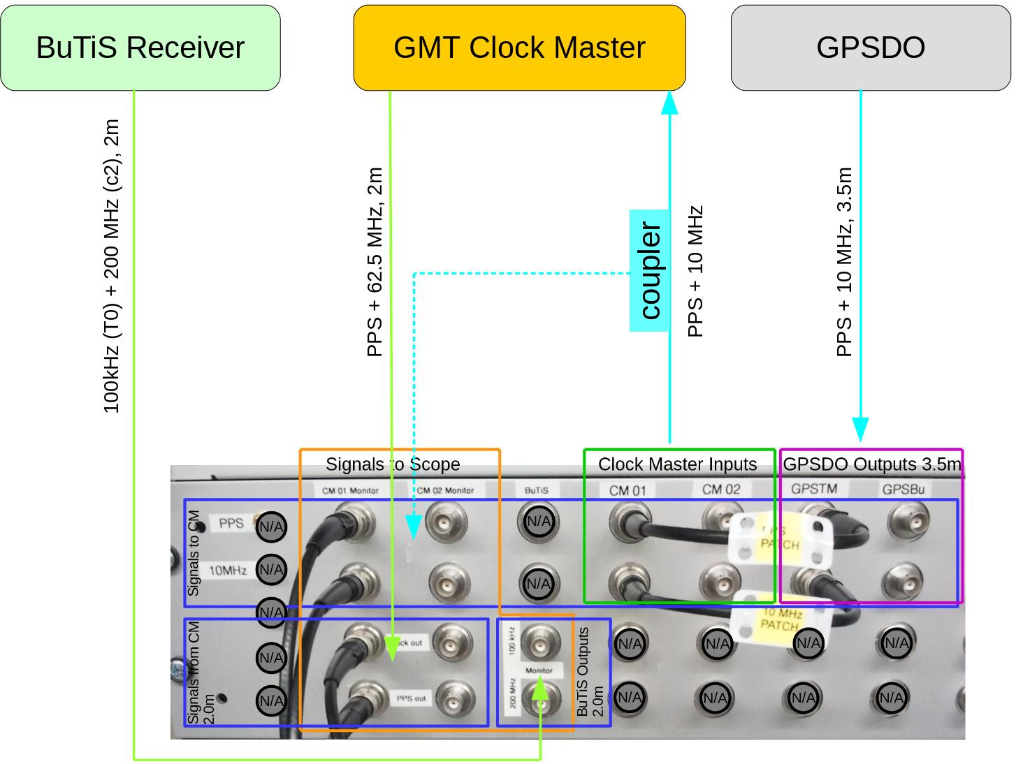 Figure: Cable plan of clock master. Indicated are GPSDO, the clock master and a BuTiS receiver station. A patch panel located in rack 54 is shown at the bottom. Two short patch cables with yellow tag connect GPSDO outputs to clock master inputs. Please note the length matched cables (3.5m) from the GPSDO as well as length matched cables (2.0m) from clock master and BuTiS. Description see text.
The figure above sketches the cables that connect GPSDO, clock master and BuTiS.
Signals to Clock Master
This is the really important part for switching between the redundant GPSDO or clock master systems. The figure shows only two cables (solid cyan arrows) for simplicity. In real life, there are two sets of four cables (redundant systems, each with PPS and 10MHz).
Figure: Cable plan of clock master. Indicated are GPSDO, the clock master and a BuTiS receiver station. A patch panel located in rack 54 is shown at the bottom. Two short patch cables with yellow tag connect GPSDO outputs to clock master inputs. Please note the length matched cables (3.5m) from the GPSDO as well as length matched cables (2.0m) from clock master and BuTiS. Description see text.
The figure above sketches the cables that connect GPSDO, clock master and BuTiS.
Signals to Clock Master
This is the really important part for switching between the redundant GPSDO or clock master systems. The figure shows only two cables (solid cyan arrows) for simplicity. In real life, there are two sets of four cables (redundant systems, each with PPS and 10MHz). - The (redundant) GPSDO is connected with length matched cables of 3.5m length to the patch panel (pink box at patch panel). The matched length makes sure, that phase offsets between the phase aligned BuTiS and White Rabbit systems are maintained when switching between GPSDO systems.
- The (redundant) clock master is connected with cables from the patch panel (green box at patch panel). It is important that all cables (PPS + 10MHz) have identical length, but the value of their length does not matter.
- Two patch cables with yellow tag allow the selection of
- GPSDO (mounted in racks 54 and 52)
- clock master (both mounted in rack 54)
- A directional coupler (cyan box) allows outcoupling a monitor signal from the signal from the GPSDO to the clock master (cyan solid arrow). This allow monitoring the PPS and 10 MHz signals at the input of the clock master without disturbing them.
- The output of the (redundant) clock master is connected with length matched cables of 2.0m length to the patch panel (green arrow to the bottom blue box).
- The output of a BuTiS reference receiver is connected with length matched cables of 2.0m length to the patch panel (green arrow to the other bottom blue box).
- The length matched cables allow to determine the phase offsets between tha actual White Rabbit and BuTiS signals.
Cabeling in Rack54
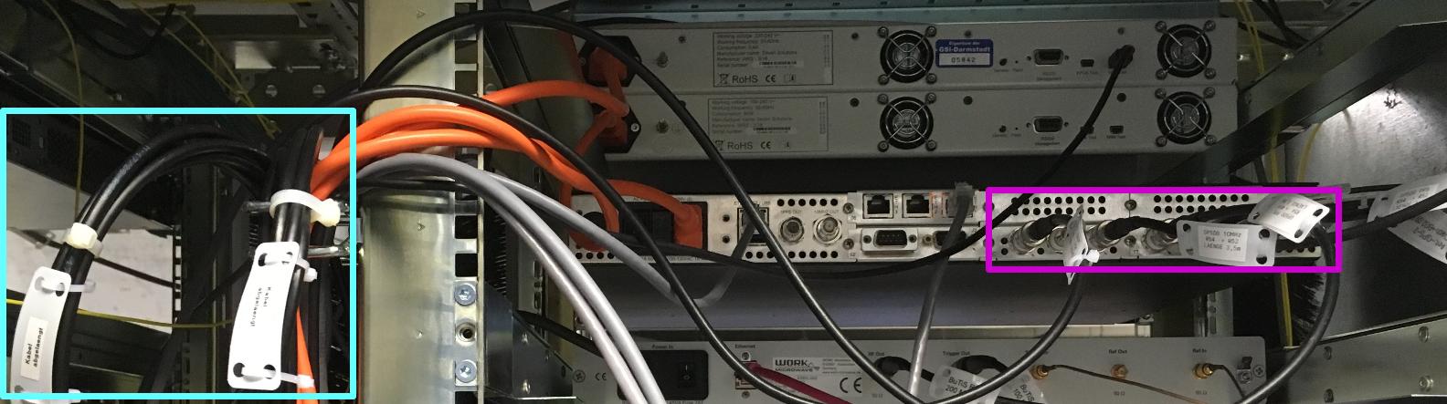 Figure: Rear view of the clock master rack. Shown are the connections at the GPSDO (pink box), two cables connecting this GPSDO to the patch panel (cyan box), two White Rabbit switches serving as redundant clock master (top) and a BuTiS reference receiver for monitoring purposes (bottom).
The figure above shows a part of the clock master rack from the rear. The two relevant modules of the GPSDO are marked by the pink box; there are three 10 MHz refclock outputs (left) and four configurable square wave outputs (right). The leftmost connectors of both modules are connected to the clock master via the patch panel (not shown) by means of length matched cables (cyan box). The rightmost connectors of both modules are connected the BuTiS centre in rack 52. The setup of the GPSDO in rack 52 is identical.
Remark: The two middle of the four square wave outputs are used to generate PPS and 10 MHz signals for other timing networks. But this is not relevant for the production system and not described here.
Figure: Rear view of the clock master rack. Shown are the connections at the GPSDO (pink box), two cables connecting this GPSDO to the patch panel (cyan box), two White Rabbit switches serving as redundant clock master (top) and a BuTiS reference receiver for monitoring purposes (bottom).
The figure above shows a part of the clock master rack from the rear. The two relevant modules of the GPSDO are marked by the pink box; there are three 10 MHz refclock outputs (left) and four configurable square wave outputs (right). The leftmost connectors of both modules are connected to the clock master via the patch panel (not shown) by means of length matched cables (cyan box). The rightmost connectors of both modules are connected the BuTiS centre in rack 52. The setup of the GPSDO in rack 52 is identical.
Remark: The two middle of the four square wave outputs are used to generate PPS and 10 MHz signals for other timing networks. But this is not relevant for the production system and not described here.
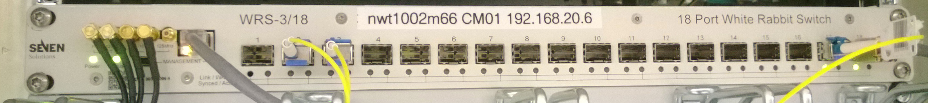 Figure: Front view of a White Rabbit switch.
The figure above shows a front view of a White Rabbit switch used a clock master. Inputs and outputs of the PPS and 10 MHz signals are on left. Both clock masters are mounted in rack 54. The cables (including the directional couplers) connecting to the patch panel in the same rack are guided on the left side (seen from the front, not shown here).
Figure: Front view of a White Rabbit switch.
The figure above shows a front view of a White Rabbit switch used a clock master. Inputs and outputs of the PPS and 10 MHz signals are on left. Both clock masters are mounted in rack 54. The cables (including the directional couplers) connecting to the patch panel in the same rack are guided on the left side (seen from the front, not shown here).
Cabeling in Rack52
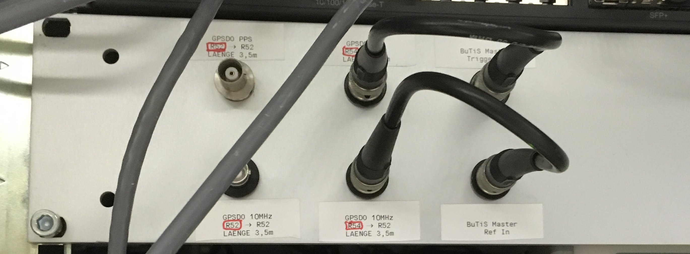 Figure: Patch panel in rack 52.
The figure above shows a patch panel in the BuTiS rack 52. Similar to the patch panel in rack 54, this patch panel allows the selection of the GPSDO that is used as reference clock input of the BuTiS center.
NB: This patch panel and the rack are under the responsibility of the BuTiS team. Don't touch!!!
-- DietrichBeck - 22 Dec 2017
Figure: Patch panel in rack 52.
The figure above shows a patch panel in the BuTiS rack 52. Similar to the patch panel in rack 54, this patch panel allows the selection of the GPSDO that is used as reference clock input of the BuTiS center.
NB: This patch panel and the rack are under the responsibility of the BuTiS team. Don't touch!!!
-- DietrichBeck - 22 Dec 2017


| I | Attachment | Action | Size | Date |
Who | Comment |
|---|---|---|---|---|---|---|
| |
wr_grandmaster.jpg | manage | 319 K | 10 Apr 2014 - 08:35 | UnknownUser | White Rabbit switch as clock master |
| |
butisCenterClockMaster1.png | manage | 65 K | 21 Dec 2017 - 08:10 | DietrichBeck | |
| |
clockmaster_rack_backside.jpg | manage | 110 K | 22 Dec 2017 - 10:14 | DietrichBeck | clock master rack from the rear |
| |
cablesClockMaster.jpg | manage | 150 K | 22 Dec 2017 - 10:48 | DietrichBeck | clock master cable plan (rack 54) |
| |
clockmaster_butisPatch.jpg | manage | 266 K | 22 Dec 2017 - 14:06 | DietrichBeck | butis patch panel |
Edit | Attach | Print version | History: r29 < r28 < r27 < r26 | Backlinks | View wiki text | Edit wiki text | More topic actions
Topic revision: r29 - 29 Oct 2019, DietrichBeck
Ideas, requests, problems regarding Foswiki? Send feedback