|
|
You are here: Foswiki>BunchBucket Web>BunchBucketDocumentation>BunchBucketDocuments>BunchBucketTestsMeasurements>BunchBucketTestMeasurement9 (13 Jul 2022, DietrichBeck)Edit Attach
June 2022: Bunch-to-Bucket ESR -> CRYRING
Table of ContentsIntroduction
A machine experiment has been performed on 7 June. The aim of this experiment was to test bunch-to-bucket transfer from ESR into CRYRING using the frequency beating method for the first time. The test has been done using hydrogen-like 198Au78+ slowed down and extracted from ESR with an energy of 10 MeV/u .Setup
See here. B2B firmware and software- mostly : v00.03.18, branch b2b_dietrich_2021-oct-14, commit 83eab29
- ESR CBU: v00.03.42, branch b2b-hotfix_dietrich_2022-jun-06, commit ad0eac5
Settings
- ESR
- h=1
- revolution time 2.451 us
- extracted 1e6 particles per bunch
- CRYRING
- h=1
- revolution time 1.223 us
- b2b
- 'beating period'
915 us - 'fine tune'
yes; FT improves extraction precision by checking neighboring rf-cycles around the theoretical beating time: Typically the beating time does not exactly coincide with an rf-cycle; thus one has to calculate which of the neighboring cycles fits better) - 'multi-beat tune'
no; MBT is a technique improves phase matching in case of very short beating time: Matching is calculated for a couple of beating periods (1, 2, 3, ...), the results are compared and the best match is chosen.
- 'beating period'
Data Acquisition
All diagnostic data of the b2b system has been recorded internally. Diagnostic of the beam has been done using theFCT Ring system that has been developed by the beam instrumentation group (credits to A. Reiter, O. Chorniy, H. Bräuning). In CRYRING not an FCT but BPM YR12DX1HT has been used as signal source. The FCT system is triggered byt the cavity signal of the ring-rf system and acquires analog data from the FCT (here: BPM). Thus it provides a 'position' of the bunch relative to the rf-signal. This measurement is repeated many times and plotted. Thus, this system allows to monitor the shape and position of bunches relative to the rf-signal as a function of time. An example is given in the figure below.
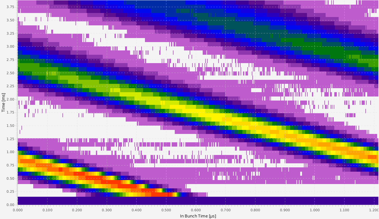 Figure: Example of a image of the FCT system. x-axis ('bunch-time'): The data shows the position and shape of the bunch relative to the the rf-signal and 'x=0' marks a trigger by the rf-signal from the DDS. y-axis: development of signal with time (here: 4 ms) The range of the x-axis equals the revolution time in CRYRING. Details see text.
The above figure shows the online view of the FCT system using a BPM signal in CRYRING. This is the data of one injection into CRYRING, there is NO summing/averaging over many injections. The beam from ESR is injected as 'coasting' beam at an arbitrary phase of the ring-rf, thus every injection looks different. At ideal conditions, one would expect a vertical line; this is not the case in this example. This is caused by a mismatch between the h=1 DDS and bunch revolution frequencies in the ring.
Figure: Example of a image of the FCT system. x-axis ('bunch-time'): The data shows the position and shape of the bunch relative to the the rf-signal and 'x=0' marks a trigger by the rf-signal from the DDS. y-axis: development of signal with time (here: 4 ms) The range of the x-axis equals the revolution time in CRYRING. Details see text.
The above figure shows the online view of the FCT system using a BPM signal in CRYRING. This is the data of one injection into CRYRING, there is NO summing/averaging over many injections. The beam from ESR is injected as 'coasting' beam at an arbitrary phase of the ring-rf, thus every injection looks different. At ideal conditions, one would expect a vertical line; this is not the case in this example. This is caused by a mismatch between the h=1 DDS and bunch revolution frequencies in the ring.
Log
The number of shifts available for the physics experiment was very limited. Thus, it was decided to perform the machine experiment in parasitic mode in parallel to the physics experiment. During the machine experiment it turned out, that CRYRING was not too well optimized for the energy of the bunch delivered from the ESR. Thus, rf-DDS and revolution frequencies did not match perfectly. However, it was decided not to perform the required energy trim as this would have changed the settings for the physics experiment, which would have caused a considerable loss in beam-time. Another caveat has been the fairly low cycle time with only one shot every ~47 seconds. In addition, a trim via ParamModi takes another cycle to become effective. As a consequence, changing the phase difference between via a trim in ParamModi would have taken about 1 1/2 minutes. To speed up the machine experiment it was decided to change the phase difference directly on the frontend using the 'FESA Explorer' which allows to change this value shot-by-shot. The machine experiment itself started around 1400 local time and took about three hours.| time [UTC] | phase diff YR [ns] | phase diff YR [°] | pic [ms] | dprev | remark |
|---|---|---|---|---|---|
| 12:40:30 | N/A | N/A | change injection at CRYRING 'coasting beam' -> 'bunch2bucket' | ||
| 12:40:47 | 612 | -180.0 | 4 | 0.0 | check reproducibility of injection |
| 12:41:30 | 612 | -180.0 | 4 | ... | ... |
| 12:42:13 | 612 | -180.0 | 4 | ... | |
| 12:42:56 | 612 | -180.0 | 4 | ... | |
| 12:43:39 | 612 | -180.0 | 4 | ... | |
| 12:44:22 | 612 | -180.0 | 4 | ... | |
| 12:45:05 | 612 | -180.0 | 4 | ... | |
| 12:45:48 | 612 | -180.0 | 4 | ... | |
| 12:46:30 | 612 | -180.0 | 4 | ... | |
| 12:47:45 | 612 | -180.0 | 4 | start measurement of injection as a function of h=1 phase difference | |
| 12:48:28 | 646 | -169.9 | 4 | ||
| 12:49:11 | 680 | -159.9 | 4 | ||
| 12:49:54 | 714 | -149.9 | 4 | ||
| 12:50:37 | 748 | -139.9 | 4 | ||
| 12:51:20 | 782 | -129.9 | 4 | ||
| 12:52:03 | 816 | -119.9 | 4 | ||
| 12:52:46 | 816 | -119.9 | |||
| 12:53:29 | 850 | -109.9 | 4 | ||
| 12:54:12 | 884 | -99.9 | 4 | ||
| 12:54:55 | 918 | -89.9 | 4 | ||
| 12:55:38 | 952 | -79.9 | 4 | ||
| 12:56:21 | 986 | -69.9 | 4 | ||
| 12:56:57 | 1020 | -59.9 | 4 | no beam | |
| 12:57:41 | 1020 | -59.9 | 4 | ||
| 12:58:24 | 1054 | -49.9 | 4 | ||
| 12:59:08 | 1088 | -39.9 | 4 | ||
| 12:59:51 | 1122 | -29.9 | 4 | ||
| 13:00:34 | 1156 | -19.9 | 4 | ||
| 13:01:17 | 1190 | -9.9 | 4 | ||
| 13:02:00 | 1224 | 0.1 | 4 | ||
| 13:02:43 | 1258 | 10.1 | 4 | ||
| 13:03:26 | 1292 | 20.1 | 4 | ||
| 13:04:09 | 1326 | 30.1 | 4 | ||
| 13:04:52 | 1360 | 40.1 | 4 | ||
| 13:05:35 | 1394 | 50.1 | 4 | ||
| 13:06:26 | 1428 | 60.1 | 4 | ||
| 13:07:09 | 1462 | 70.1 | 4 | ||
| 13:07:52 | 1496 | 80.1 | 4 | ||
| 13:08:35 | 1530 | 90.1 | 4 | ||
| 13:09:18 | 1564 | 100.1 | 4 | ||
| 13:10:01 | 1598 | 110.1 | 4 | ||
| 13:10:44 | 1632 | 120.1 | 4 | ||
| 13:11:27 | 1666 | 130.1 | 4 | ||
| 13:12:10 | 1700 | 140.1 | 4 | ||
| 13:12:53 | 1734 | 150.1 | 4 | ||
| 13:13:36 | 1768 | 160.1 | 4 | ||
| 13:14:19 | 1802 | 170.1 | 4 | ||
| 13:15:15 | 1836 | 180.1 | SIS18 kicker failure | ||
| 13:16:11 | 1836 | 180.1 | |||
| 13:17:07 | 1836 | 180.1 | |||
| 13:18:03 | 1836 | 180.1 | |||
| 13:18:46 | 1836 | 180.1 | 4 | kicker back | |
| 13:19:29 | 1870 | 190.1 | 4 | ||
| 13:20:12 | 1904 | 200.2 | 4 | ||
| 13:20:55 | 1938 | 210.2 | 4 | end of measurement | |
| 13:21:38 | 1088 | -39.9 | |||
| 13:22:21 | 1088 | -39.9 | 8 | ||
| 13:23:04 | 1788 | 166.0 | |||
| 13:23:47 | 1698 | 139.5 | 8 | ||
| 13:24:30 | 1088 | -39.9 | 8 | ||
| 13:25:13 | 1098 | -37.0 | 8 | ||
| 13:25:56 | 1098 | -37.0 | 8 | ||
| 13:26:39 | 1108 | -34.0 | 8 | ||
| 13:27:22 | 1078 | -42.9 | 8 | ||
| 13:28:05 | 1078 | -42.9 | 8 | ||
| 13:28:48 | 1068 | -45.8 | 8 | ||
| 13:29:31 | 1678 | 133.7 | |||
| 13:30:14 | 1068 | -45.8 | 8 | 1.40 | adjust dprev |
| 13:30:57 | 1068 | -45.8 | 1.44 | ||
| 13:31:40 | 1068 | -45.8 | 1.36 | ||
| 13:32:23 | 1068 | -45.8 | 1.46 | ||
| 13:33:06 | 1068 | -45.8 | 1.46 | ||
| 13:33:49 | 1068 | -45.8 | 1.46 | ||
| 13:34:32 | 1068 | -45.7 | 8 | 1.46 | |
| 13:35:15 | 1068 | -45.7 | 8 | 1.46 | found 'good' dprev |
| 13:36:02 | 1068 | -45.9 | 8 | 0.0 | verify previous result |
| 13:36:45 | 1068 | -45.9 | 8 | 0.0 | |
| 13:37:28 | 1068 | -45.9 | |||
| 13:38:15 | 1068 | -45.7 | |||
| 13:38:58 | 1068 | -45.7 | 8 | 1.46 | back to 'good' dprev, bad value for DDS phase difference |
| 13:39:41 | 1300 | 22.6 | 8 | re-adjust phase difference | |
| 13:40:24 | 1600 | 110.9 | 8 | ||
| 13:41:07 | 1600 | 110.9 | |||
| 13:41:50 | 1600 | 110.9 | 12 | ||
| 13:42:33 | 1600 | 110.9 | |||
| 13:43:16 | 1600 | 110.9 | |||
| 13:43:59 | 1620 | 116.8 | 12 | ||
| 13:44:42 | 1620 | 116.8 | 12 | ||
| 13:45:26 | 1640 | 122.7 | 12 | ||
| 13:46:09 | 1660 | 128.6 | 12 | ||
| 13:46:52 | 1700 | 140.4 | 12 | try to improve DDS phase difference | |
| 13:47:35 | 1740 | 152.1 | 12 | ||
| 13:48:18 | 1780 | 163.9 | 12 | ||
| 13:49:01 | 1780 | 163.9 | |||
| 13:49:44 | 1780 | 163.9 | |||
| 13:50:27 | 1780 | 163.9 | |||
| 13:51:10 | 1780 | 163.9 | |||
| 13:51:53 | 1780 | 163.9 | 10 | ||
| 13:52:36 | 1780 | 163.9 | 10 | 1.47 | |
| 13:53:19 | 1780 | 164.0 | 10 | 1.47 | |
| 13:54:02 | 1780 | 164.0 | 1.47 | increase gap voltage | |
| 13:54:49 | 1780 | 163.9 | 1.47 | decrease gap voltage below initial value | |
| 13:55:32 | 1780 | 163.9 | 1.45 | ||
| 13:56:15 | 1740 | 152.1 | 10 | 1.45 | |
| 13:56:58 | 1780 | 163.9 | 10 | ... | |
| 13:57:41 | 1700 | 140.3 | |||
| 13:58:24 | 1660 | 128.6 | 10 | ||
| 13:59:07 | 1700 | 140.3 | |||
| 13:59:54 | 1700 | 140.3 | 10 | ||
| 14:00:37 | 1700 | 140.3 | |||
| 14:01:19 | 1700 | 140.3 | back to gap voltage at 13:54:02 | ||
| 14:02:06 | 1700 | 140.4 | 10 | 1.46 | |
| 14:02:49 | 1750 | 155.1 | 10 | ... | |
| 14:03:32 | 1650 | 125.7 | 10 | this seems to be the best value for the DDS phase difference | |
| 14:04:15 | 1650 | 125.7 | |||
| 14:04:58 | 1650 | 125.7 | |||
| 14:05:41 | 1650 | 125.7 | 10 | ||
| 14:06:28 | 1650 | 125.7 | |||
| 14:07:11 | 1650 | 125.7 | 1.47 | ||
| 14:07:54 | 1650 | 125.7 | ... | ||
| 14:08:37 | 1650 | 125.7 | 10 | increase gap voltage even more | |
| 14:09:20 | 1650 | 125.7 | further increase gap voltage | ||
| 14:10:03 | 1650 | 125.7 | |||
| 14:10:46 | 1650 | 125.7 | 10 | ||
| 14:11:33 | 1650 | 125.7 | 10 | 1.48 | change dprev |
| 14:12:16 | 1650 | 125.7 | 100 | 1.48 | |
| 14:13:03 | 1650 | 125.7 | 200 | 1.42 | |
| 14:13:46 | 1650 | 125.7 | 500 | ... | |
| 14:14:29 | 1650 | 125.7 | |||
| 14:15:12 | 1650 | 125.7 | 10 | ||
| 14:15:55 | 1650 | 125.7 | |||
| 14:16:42 | 1650 | 125.5 | 10 | 0.0 | |
| 14:17:25 | 1100 | -36.3 | 10 | ... | |
| 14:18:08 | 1150 | -21.6 | 10 | ||
| 14:18:51 | 1200 | -6.9 | 10 | ||
| 14:19:34 | 1050 | -51.0 | |||
| 14:20:17 | 1000 | -65.8 | 10 | ||
| 14:21:00 | 950 | -80.5 | |||
| 14:21:43 | 950 | -80.5 | |||
| 14:22:26 | 1000 | -65.8 | 10 | ||
| 14:23:09 | 1025 | -58.4 | |||
| 14:23:52 | 1035 | -55.5 | 10 | ||
| 14:24:35 | 1035 | -55.5 | |||
| 14:25:18 | 1035 | -55.5 | |||
| 14:26:01 | 1035 | -55.5 | |||
| 14:26:44 | 1645 | 124.0 | |||
| 14:27:27 | 1645 | 124.0 | 500 | 0.0 | compare this figure with no dprev to the one from 14:13:46 |
| 14:28:10 | 1645 | 124.0 | 500 | ||
| 14:28:53 | 1035 | -55.5 | |||
| 14:29:36 | 1035 | -55.5 | |||
| 14:30:19 | 1035 | -55.5 | |||
| 14:31:02 | 1035 | -55.5 | |||
| 14:31:45 | 1035 | -55.5 | |||
| 14:32:28 | 1035 | -55.5 | |||
| 14:33:11 | 1035 | -55.5 | |||
| 14:33:54 | 1035 | -55.5 | |||
| 14:34:37 | 1035 | -55.5 | |||
| 14:35:20 | 1035 | -55.5 | |||
| 14:36:03 | 1035 | -55.5 | |||
| 14:36:46 | 1035 | -55.5 | |||
| 14:37:29 | 1035 | -55.5 | |||
| 14:38:12 | 1035 | -55.5 | 10 | check debunching over various time spans | |
| 14:38:55 | 1035 | -55.5 | |||
| 14:39:38 | 1035 | -55.5 | 10 | ||
| 14:40:21 | 1035 | -55.5 | 10 | ||
| 14:41:04 | 1035 | -55.5 | 20 | ||
| 14:41:47 | 1035 | -55.5 | |||
| 14:42:30 | 1035 | -55.5 | 20 | strong variation in beam intensity between shots | |
| 14:43:13 | 1035 | -55.5 | 20 | ||
| 14:43:56 | 1035 | -55.5 | 20 | ||
| 14:44:39 | 1035 | -55.5 | 20 | ||
| 14:45:22 | 1035 | -55.5 | |||
| 14:46:05 | 1035 | -55.5 | ion source is dead, ion source service, end of experiment |
Results
Injection as Coasting Beam vs. Fixed Phase
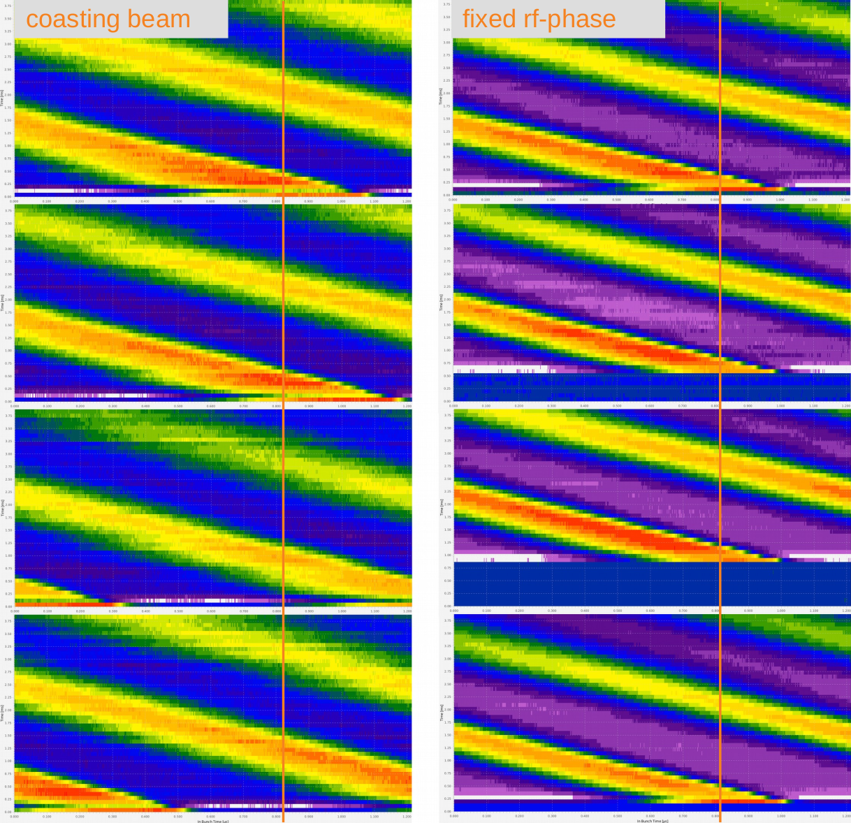 Figure: Comparison of four injection as coasting beam (left) and at fixed rf-phase (right). The two vertical lines serve to guide the eye. Details see text.
The figure above compares the two scenarios where beam is injected as coasting (not locked to rf-phase) and at fixed rf-phase (using frequency beating). When injected as coasting beam, injection is done at an arbitrary rf-phase. This can be seen on the left, where the detected bunch signal 'jumps' to a different phase time with each injection. The situation is different on the right. Here, the bunch-2-bucket system uses the frequency beating method to achieve injection at a fixed rf-phase (of CRYRING) and the BPM system detects the injected bunch always at the same bunch time. When the frequency beating method is employed, the bunch-2-bucket system waits until the phase difference between the rf-signals of ESR and CRYRING equals the set-value in ParamModi. This 'waiting' can be seen on the right, where the time of injection (y-axis) varies in a range of about 1 ms.
Figure: Comparison of four injection as coasting beam (left) and at fixed rf-phase (right). The two vertical lines serve to guide the eye. Details see text.
The figure above compares the two scenarios where beam is injected as coasting (not locked to rf-phase) and at fixed rf-phase (using frequency beating). When injected as coasting beam, injection is done at an arbitrary rf-phase. This can be seen on the left, where the detected bunch signal 'jumps' to a different phase time with each injection. The situation is different on the right. Here, the bunch-2-bucket system uses the frequency beating method to achieve injection at a fixed rf-phase (of CRYRING) and the BPM system detects the injected bunch always at the same bunch time. When the frequency beating method is employed, the bunch-2-bucket system waits until the phase difference between the rf-signals of ESR and CRYRING equals the set-value in ParamModi. This 'waiting' can be seen on the right, where the time of injection (y-axis) varies in a range of about 1 ms.
Variation of ESR-CRYRING RF-Phase Difference and Data Analysis
The only free parameter of bunch-2-bucket transfer system is the phase difference between the ESR and CRYRING h=1 group DDS signals. This has been varied in steps of 34 ns (10° of CRYRING h=1).Pre-Processing
During this machine experiment the analysis has been hampered by the fact, that h=1 frequency has been slightly higher than the revolution frequency of the bunch in the ring (see figure and discussion in the section Data Acquisition). However, the h=1 frequency is known and the revolution frequency can be determined from the measured data. Thus, it is possible to pre-process the data as shown below.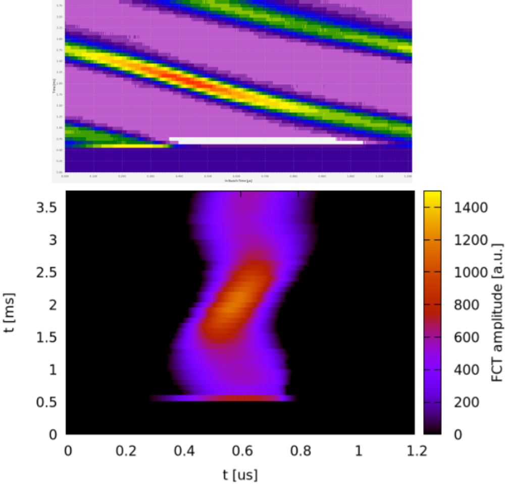 Figure: Pre-processing of data. Raw image (top) and image of pre-processed data (bottom). This example shows a phase difference of 1285 ns between ESR and CRYRING h=1 DDS signals. See text for details.
The figure above compares images of raw and pre-processed data. As an example, the oscillation of the bunch in the bucket is barely visible in the original data but becomes very clear after pre-processing. In the pre-processing, the original data of each line is shifted according to the difference between h=1 (DDS) and revolution (bunch) frequencies. The result are data that would have been obtained in case the FCT system would have been triggered using the correct revolution frequency.
Figure: Pre-processing of data. Raw image (top) and image of pre-processed data (bottom). This example shows a phase difference of 1285 ns between ESR and CRYRING h=1 DDS signals. See text for details.
The figure above compares images of raw and pre-processed data. As an example, the oscillation of the bunch in the bucket is barely visible in the original data but becomes very clear after pre-processing. In the pre-processing, the original data of each line is shifted according to the difference between h=1 (DDS) and revolution (bunch) frequencies. The result are data that would have been obtained in case the FCT system would have been triggered using the correct revolution frequency.
Analysis
There is just one free parameter for the bunch-2-bucket transfer system - the phase difference between the h=1 group DDS signals of the two rings. When taking a series of data with the FCT system varying the phase difference, it is an open question how to analyze the data in a quantitative way. As a first approach the formula for entropy S = Σ pi * log pi has been applied to the data for each injection, wherei is the bin number along the x-axis and pi is the sum of all y-values in that bin (???). Thus, one obtains an value for the entropy for each phase. The calculated entropy values are then plotted as a function of phase.
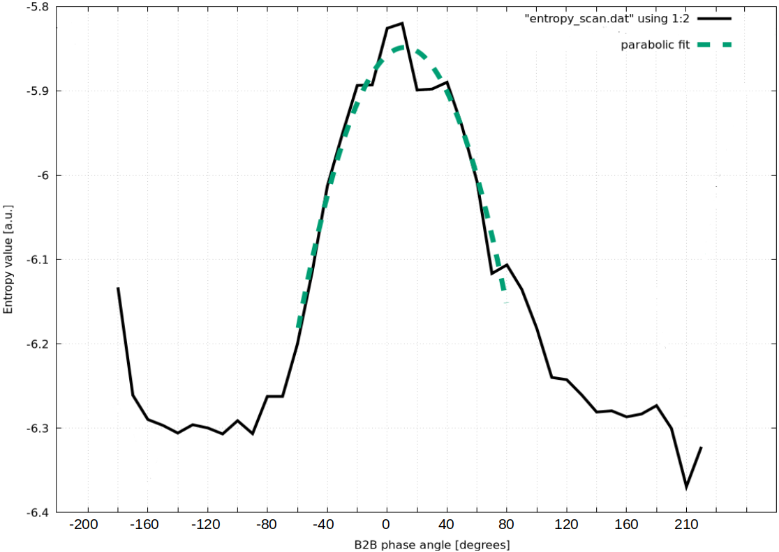 Figure: Black line: Entropy (y-axis) of the acquired data as a function of h=1 phase difference (x-axis, angle is in units of CRYRING h=1 frequency). Green, dashed line: Fit of a parabolic shape. See text.
The result of the above procedure is shown in the figure above. After plotting the entropy in arbitrary units as a function of phase difference between the two h=1 group DDS signals, a parabolic shape is fitted to the data points to determine the the optimum phase for injection into CRYRING. The FWHM of the peak is about 90°.
Figure: Black line: Entropy (y-axis) of the acquired data as a function of h=1 phase difference (x-axis, angle is in units of CRYRING h=1 frequency). Green, dashed line: Fit of a parabolic shape. See text.
The result of the above procedure is shown in the figure above. After plotting the entropy in arbitrary units as a function of phase difference between the two h=1 group DDS signals, a parabolic shape is fitted to the data points to determine the the optimum phase for injection into CRYRING. The FWHM of the peak is about 90°.
Variation of DDS Frequency Detuning and Gap Voltage
The above measurements have been performed under non-ideal conditions, as the revolution frequency of the bunch in CRYRING did not exactly match the h=1 group DDS frequency. The dilemma is shown in the following figure.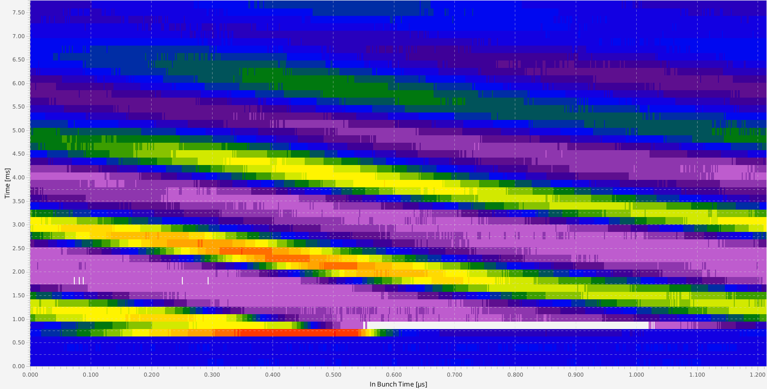
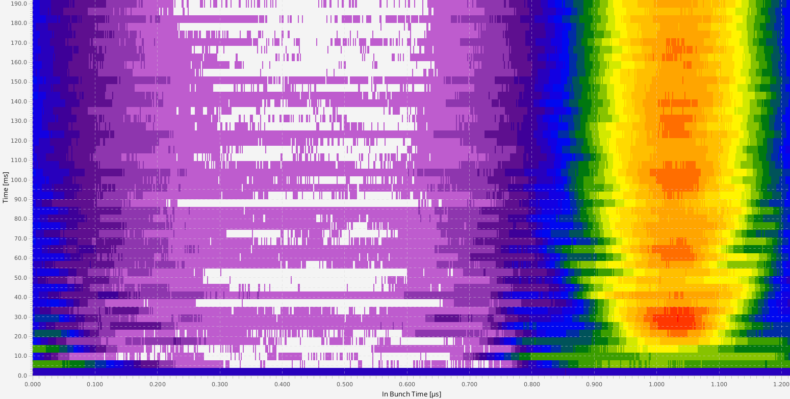
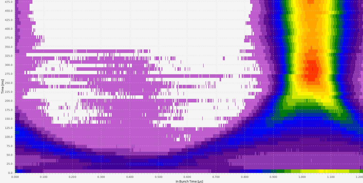 Figure: Debunching as a consequence of mismatch between revolution frequency and h=1 DDS frequency. Top: observation time is 10 ms after injection; bottom: observation time is 500 ms after injection.
As can be seen in the figure above - although the bunch is captured in the center of a bucket - it is debunched after a few milliseconds. Fortunately, the acceptance of CRYRING is that large, that most of the ions remain stored and the ions are cooled by the electron cooler.
The main four parameters for tuning injection into a bucket are the following
Figure: Debunching as a consequence of mismatch between revolution frequency and h=1 DDS frequency. Top: observation time is 10 ms after injection; bottom: observation time is 500 ms after injection.
As can be seen in the figure above - although the bunch is captured in the center of a bucket - it is debunched after a few milliseconds. Fortunately, the acceptance of CRYRING is that large, that most of the ions remain stored and the ions are cooled by the electron cooler.
The main four parameters for tuning injection into a bucket are the following - bunch-2-bucket transfer system
- phase difference between h=1 group DDSs of ESR and CRYRING (parameter of bunch-2-bucket system)
- other parameters in ParamModi
- injection energy (here: out of scope)
- h=1 group DDS frequency at CRYRING (parameter
dprev Injektion) and - the gap voltage of the rf-cavity in CRYRING
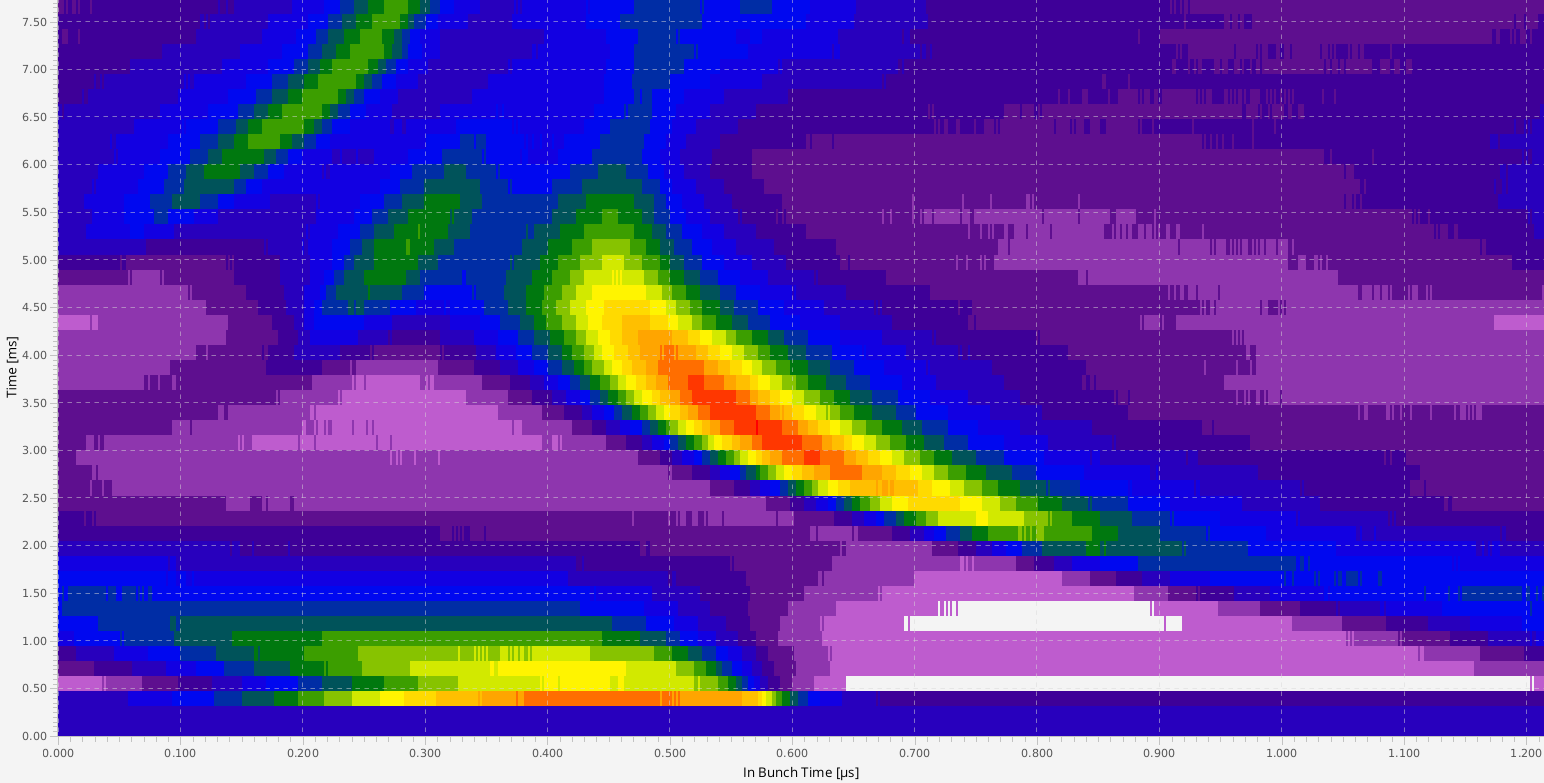
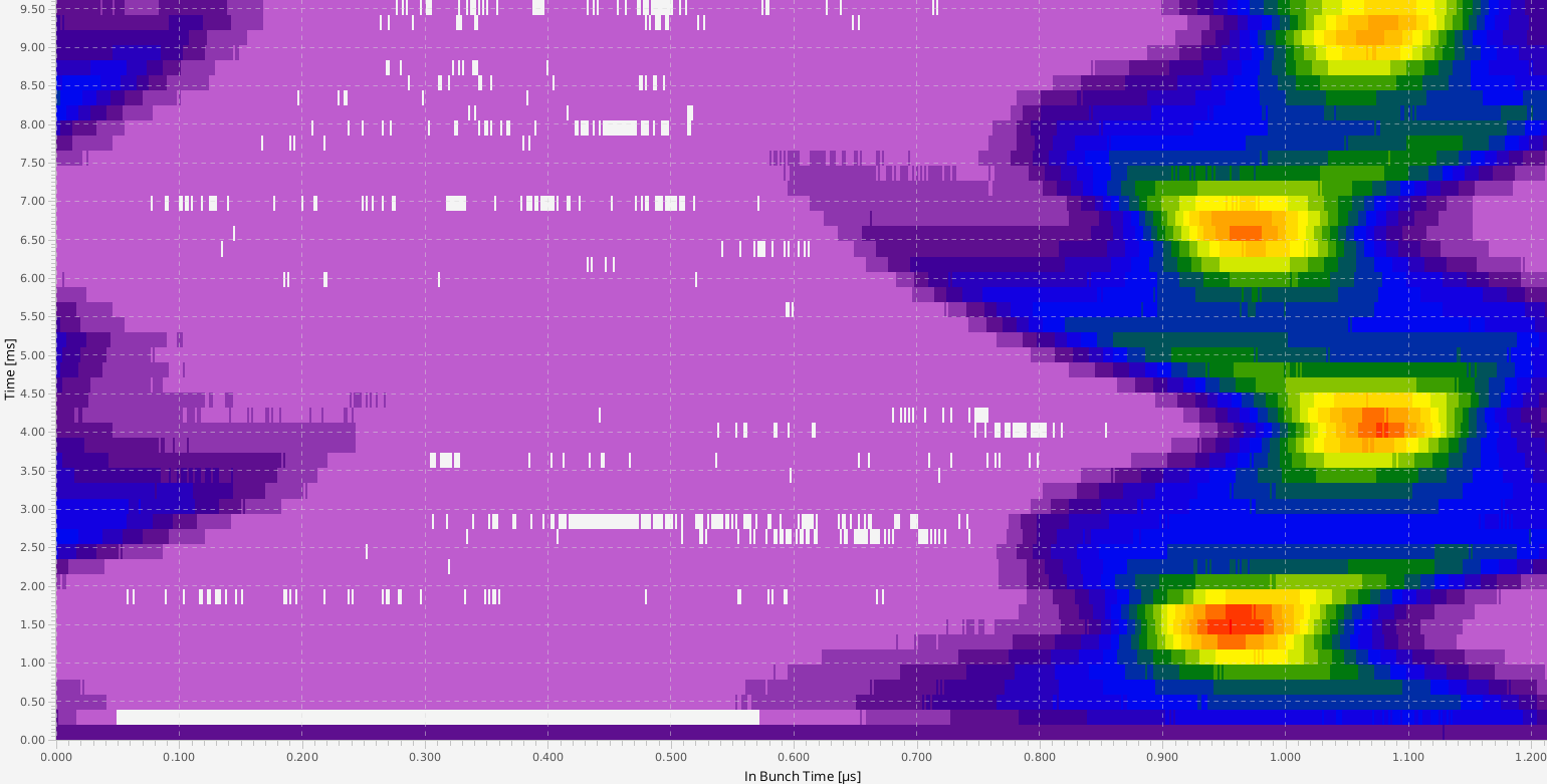
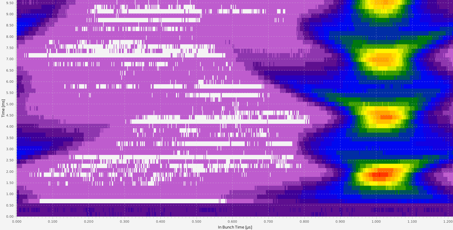
 Figures from top to bottom: Injection with dprev tuned, phase re-tuned, gap voltage increased, voltage increased further and for long observation time. Please note, that the observation time is changed from 8 ms (figure 1,2) to 10 ms (figure 3, 4) and finally to 200 ms (figure 5). See text for details.
As a first step, the frequency of the h=1 Group DDS was matched to the revolution frequency of the bunch in CRYRING. As a result, the phase difference of the bunch-2-bucket system is wrong (1st figure from top). As a 2nd step, the phase difference was adjusted again. Now, the bunch is trapped in the bucket. However, the changed rf-frequency does no longer fit to the magnetic field settings and the bunch starts oscillating in the longitudinal direction (2nd figure). This (dipole?) oscillation could be suppressed by increasing the gap voltage, but the bunch starts (quadruple?) oscillating. Anyhow, the bunch is stably trapped for in the bucket and ready for cooling (bottom image, 200 ms observation time).
Figures from top to bottom: Injection with dprev tuned, phase re-tuned, gap voltage increased, voltage increased further and for long observation time. Please note, that the observation time is changed from 8 ms (figure 1,2) to 10 ms (figure 3, 4) and finally to 200 ms (figure 5). See text for details.
As a first step, the frequency of the h=1 Group DDS was matched to the revolution frequency of the bunch in CRYRING. As a result, the phase difference of the bunch-2-bucket system is wrong (1st figure from top). As a 2nd step, the phase difference was adjusted again. Now, the bunch is trapped in the bucket. However, the changed rf-frequency does no longer fit to the magnetic field settings and the bunch starts oscillating in the longitudinal direction (2nd figure). This (dipole?) oscillation could be suppressed by increasing the gap voltage, but the bunch starts (quadruple?) oscillating. Anyhow, the bunch is stably trapped for in the bucket and ready for cooling (bottom image, 200 ms observation time).
Phase-Locked Extraction
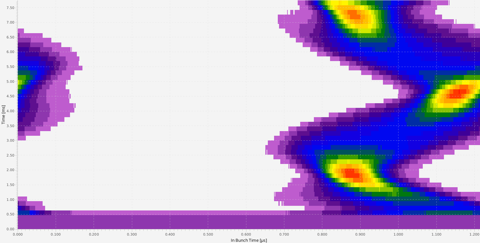
In previous beam-times extraction at CRYRING has always been done in event-triggered mode. These events have been scheduled by the LSA settings management system. Being an off-line system, LSA is unaware of the actual DDS phase at CRYRING. Thus, the kicker was firing at a different rf-phase from shot-to shot. Sometimes the bunch was kicked in the right moment but sometimes not. Starting with the beam-time 2022, the bunch-to-bucket system has been installed at CRYRING too and rf-locked extraction is now possible. Figure: Beam extracted from CRYRING diagnosed by the CUPID system. Top to bottom: Six different extractions from CRYRING. The 'crosshair' marks the center of the diagnostic system.
As can be seen in the figure above, the extracted beam is always observed close to the center of detection region and remains fixed at the same position. Compared to previous years, this allows for much better conditions for physics experiments using beam extracted from CRYRING.
Figure: Beam extracted from CRYRING diagnosed by the CUPID system. Top to bottom: Six different extractions from CRYRING. The 'crosshair' marks the center of the diagnostic system.
As can be seen in the figure above, the extracted beam is always observed close to the center of detection region and remains fixed at the same position. Compared to previous years, this allows for much better conditions for physics experiments using beam extracted from CRYRING.
Summary
Bunch-to-bucket transfer from ESR to CRYRING has been demonstrated successfully. The machine experiment has been performed parasitically to the ongoing physics program at CRYRING. This was possible due to the large acceptance as well as the electron cooler; the bunch remains stored (even with wrong rf-phase) and the cooler is able cool the beam independently of what happens at injection. The energy of CRYRING was slightly detuned with respect to the energy of the bunches delivered by ESR. As a result, the revolution frequency did not match the one from the DDS rf-cavity. However, it was possible to achieve 'stable' transfer into buckets after DDS phase difference (ESR, CRYRING) , DDS frequency (CRYRING) have been tuned and the gap voltage of the rf-cavity increased. Furthermore, rf-triggered extraction was implemented at CRYRING and was available for routine operation in the 2022 beam-time. Compared to previous beam-times at CRYRING, rf-triggered extraction allows for stable and reproducible delivery of beam to physics experiments. -- DietrichBeck - 11 Jul 2022

| I | Attachment | Action | Size | Date | Who | Comment |
|---|---|---|---|---|---|---|
| |
2022-06-06_17-19-07_YR-injection-example.png | manage | 50 K | 11 Jul 2022 - 12:41 | DietrichBeck | BPM example YR injection |
| |
2022-06-07_13-39-04_yr-inj_no1-dprev-tuned.png | manage | 57 K | 13 Jul 2022 - 09:32 | DietrichBeck | dprev tuned |
| |
2022-06-07_13-40-37_yr-inj_no2-phase-tuned.png | manage | 51 K | 13 Jul 2022 - 09:32 | DietrichBeck | dprev and phase tuned |
| |
2022-06-07_14-09-15_yr-inj_no3-gap-voltage-inc1.png | manage | 59 K | 13 Jul 2022 - 09:33 | DietrichBeck | dprev and phase tuned, gap voltage increased |
| |
2022-06-07_14-11-53_yr-inj_no4-gap-voltage-inc2.png | manage | 62 K | 13 Jul 2022 - 09:33 | DietrichBeck | dprev and phase tuned, gap voltage increased further |
| |
2022-06-07_14-13-43_yr-inj_no5-with-cooler.png | manage | 71 K | 13 Jul 2022 - 09:34 | DietrichBeck | dprev and phase tuned, gap voltage increased further and longer observation time |
| |
2022-06-07_17-06-35_yr-ext.png | manage | 487 K | 12 Jul 2022 - 14:02 | DietrichBeck | beam extracted from CRYRING |
| |
22-06-07_13-22-29_yr-inj_debunching.png | manage | 59 K | 12 Jul 2022 - 12:42 | DietrichBeck | debunching after injection |
| |
22-06-07_14-28-20_yr-inj_debunching-long.png | manage | 63 K | 12 Jul 2022 - 13:28 | DietrichBeck | debunching and cooling |
| |
esr-yr_coasting-vs-fixedphase.png | manage | 1 MB | 11 Jul 2022 - 14:59 | DietrichBeck | coasting beam vs fixed phase |
| |
pre-processing_phase10.png | manage | 245 K | 12 Jul 2022 - 07:46 | DietrichBeck | data pre-processing |
| |
yr-inj_entropy-scan.png | manage | 147 K | 12 Jul 2022 - 11:28 | DietrichBeck | entropy scan |
Edit | Attach | Print version | History: r7 < r6 < r5 < r4 | Backlinks | View wiki text | Edit wiki text | More topic actions
Topic revision: r7 - 13 Jul 2022, DietrichBeck
- Toolbox
-
 Create New Topic
-
 Index
Index
-
 Search
-
 Changes
-
 Notifications
-
 RSS Feed
-
 Statistics
-
 Preferences
Ideas, requests, problems regarding Foswiki? Send feedback