|
|
You are here: Foswiki>Applications Web>AppGuiComponentsMain>AppGuiComponentsSchemaWidget>AppGuiComponentsSchemaWidgetAcceleratorSchema (02 Mar 2023, AnnekeWalter)Edit Attach
AcceleratorSchema
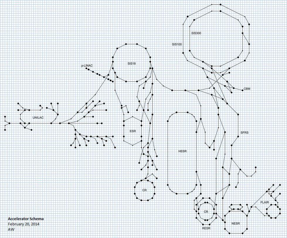
The SchemaWidget displays a schematic representation of the GSI/FAIR accelerator instead of a realistic one to achieve a more descriptive visualization: Very busy areas with many details are relatively larger in the schema, and very large structure with few details are relatively smaller. The schema tries to retain the relative positioning and sizing of different accelerator structures while applying the aforementioned visualization improvements. The schema was created as an Inkscape vector graphics. It was based on several plans of the accelerator and, originally, the definitions of accelerator sections of the OperDB (see picture on the right).In the future (2017 and onwards), the schema will base its section definitions on the accelerator zones of LSA.

How to Use the Schema SVG
- To change the schema: Get the current SVG file and open it with Inkscape.
- To read a SectionModel directly from the SVG: A demo tool called SvgReader is available in the SchemaWidget project , however the tool may be moved to a different project in the future.
- To import the schema data from the SVG into a database: As of 01/2017, AP is planning to provide FlywayDB-compatible support for importing schema data into the LSA database(s). A demo tool called SchemaData2Sql is available in the SchemaWidget project, however that is not yet the finished version and the tool may be moved to a different project in the future.
Get Current Svg File
It is planned (as of 01/2017) that a "master schema SVG file" will be centrally stored under version control. Until that is the case, a more or less up-to-date version of the SVG (though not necessarily "the" master file) can be found in the SchedulingApp project (src/main/resources).Layers
Different parts of the schema are stored on different layer, providing logical grouping and the possibility to hide layers you do not currently need. Suggestion: Lock all layers you do not currently need, this makes it harder to accidently change/delete something as you cannot accidently select something from a locked layer.- Toggle layers view with Ctrl+Shift+L
- Select the layer you want to work with by clicking
- Show/hide a layer with the eye symbol
- Lock/unlock layers for editing with the lock symbols.
XML Editor
Open Inkscape's XML Editor with Ctrl+Shift+X to see and edit the SVG's xml.Defining Schema Data
All coordinates should be placed on multiples of 5 - see how to display and snap to a grid below.Defining Sections
Each section must be represented by a Group (svg:g) with a unique "id" attribute and a unique "name" attribute. When a SectionModel is read from the SVG, the resulting SchemaSection will have the specified name. If the unique id was formatted as S1234 (note: format may change), the SchemaSection's id will be 123. Otherwise, the resulting SchemaSection will have an arbitrary id. The subsections of a section are defined as children of the section Group. Each subsection must be a straight Path (svg:path) with a "position" attribute. The "position" attribute describes the order of subsections within a section. If it is missing or multiple subsections have the same value for their "position" attributes, the order of subsections for the section is arbitrary and a warning will be logged when reading a SectionModel from the SVG. The coordinates of the start and end point of a subsection are computed from the Path's "d" attribute. Simple translations (attribute "transform") are correctly taken into account.Defining Named Schema Points
SchemaPoints can have a name to identify them. To specify such points, use a Circle (svg:circle). The Circle's center (attributes "cx" and "cy") describes the coordinates of the schema point. Simple translations (attribute "transform") are correctly taken into account. The circle also needs a "name" attribute that describes the name. Ideally, the master SVG file should already contain at least one sample Circle that can be copied and reused, as Inkscape cannot create true Circles, but only Paths that look like circles.Display and Snap to Grid
To have all the points of subsections aligned nicely, you should display a fitting alignment grid and activate the "snap to grid" functionality to let the vector vertices snap to the grid intersections of the alignment grid. This ensures that all coordinates that will be later extracted are perfect multiples of 5. The master SVG is configured to contain and automatically display a fitting alignment grid.- Only if the grid is not already available!!!
- Define the alignment grid: File -> Document Properties (or Ctrl+Shift+D).
- Go to Grids and define a grid:
- check "enabled", "visible", and "snap to visible grid lines only"
- grid units: px
- origin x and y: 0
- spacing x and y: 5
- Show/hide the alignment grid with #
- Activate/deactivate snap to grid functionality with a click on the grid button

SchemaSvgGridAlignmentTest that checks the SVG for proper alignment.
Fixing the grid alignment if it got broken
There is a Unit test calledSchemaSvgGridAlignmentTest that checks the SVG for proper alignment.
If the grid alignment got broken and the schema points have ugly, non-integer coordinates, you have to manually fix the problem. - Open SVG in Inkscape
- Let's start with a nice page size: File -> Document Properties -> Page -> "Resize page to content" with e.g. margin 200 -> "Resize to drawing or selection"
- Look at each layer in XML Editor, remove any translations. This will move the contained data out of the page - we will fix this later!
- Re-create grid as described above with Origin 0,0 ; Spacing 5,5
- Named Points Layer
- Select all points
- Grab one point and move to the grid on the page, making sure to snap to grid intersections.
- Use Unit test to see which points are still broken. Move their points manually and snap them.
- Section Layer
- Optional: Remove markers at path endpoints. This helps to better see what you are doing, but re-adding them is fiddly.
- Open the SVG in a text editor and replace all entries like "stroke-opacity:1;marker-start:url(#DotL);marker-mid:url(#DiamondM);marker-end:url(#DotL)" with just "stroke-opacity:1;"
- When you are done, go through all the changes in e.g. Meldand undo those style changes.
- Select all sections
- Grab one section and move to the grid on the page, making sure to snap the endpoint of a section path to grid intersections.
- Sometimes, Inkscape doesn't offer "snap to grid intersection". Just keep trying, maybe grab another section, ...
- Use Unit test to see which (sub-)sections are still broken. Snap them manually.
- Optional: Remove markers at path endpoints. This helps to better see what you are doing, but re-adding them is fiddly.
- FAIR Beam Transfer Letters Layer
- Snapping to grid is not important for this layer. Just manually move it to wherever it fits correctly.
- When you are done, have a quick look at the changes to the SVG with e.g. Meld. For the various paths and objects, you should only have changes to the path definitions or translations.
- Inkscape will also chance some stuff like the viewport - obviously, this is irrelevant. Leave it in or remove as you desire.
Printable grid
Sometimes it can be useful to print out the alignment grid with the schema, but Inkscape does not support this. However, you can create a "Printable Grid" layer with a grid identical to the alignment grid that can be printed with the schema.- Create the grid:
- Extensions -> Render -> Grid
- Line width 1 px, line spacing as desired / like the alignment grid (5 px)
- After creating the grid: color of the grid lines can be changed by selecting all the grid lines (Edit -> Select All) and setting the desired color as the stroke color.
- Only show this layer for printing, then hide it again! Otherwise the effort of rendering this layer will slow down Inkscape to a crawl.
Editing, adding and removing sections
- Select the Sections layer and unlock it (open lock symbol).
- Open the XML Editor (Ctrl+Shift+X) to see which section/subsection you are editing.
- Go to File -> Inkscape Preferences -> Tools -> Node and check "Always show outline" and "Show path direction on outlines".
Editing
- Select section Group (use
 , click on section)
- Activate "Edit Path by Nodes" (F2 or
 )
)
- Vertices of the subsection Paths can now be moved around separately.
- Make sure the subsection Path has the expected direction (the start point should be where the particle beam enters the subsection, the end point should be where the particle beam exits the subsection):
- When "Edit Path by Nodes" (F2 or ) is active, select the subsection Path. A little half-arrow should signal the Path direction (if not, activate it under File -> Inkscape Preferences -> Tools -> Node and check "Always show outline" and "Show path direction on outlines" ).
- To reverse the direction of a Path, go to Path -> Reverse or use Shift+R.
- When "Edit Path by Nodes" (F2 or
- To split a subsection Path in two: Select it, then use "Insert new Nodes into selected segments" (
 ) to insert a new node. Then click "Break Path at selected nodes" (
 ) or use Shift+B to create two subsections. Use the XML Editor to make sure both subsection Paths have a correct "position" attribute!
- Add a new subsection: Either split an existing subsection Path and edit it, or copy an existing subsection Path and edit it. In both cases, use the XML Editor to make sure all subsection Paths are in the correct section Group and have a correct "position" attribute!
- Note: If subsections A and B are connected at a point P, there are actually two points for P in the schema - PA (end point of A) und PB (start point of B). When A is shortened and PA is moved, B should be adapted as well by moving PB so PA and PB are at the same location again. It is ok to have gaps between the subsections of a section if that is what you want though!
Adding a section
- Select an existing section with
- Copy and paste the section (Ctrl+C, Ctrl+V)
- Edit the section as described above.
- Use the XML Editor to make sure the section Group has a valid, unique "name" attribute. You may also want to make sure it has its id attribute in the correct format.
Removing
- Select the section with
- Press Del button
Obtaining Schema Data from the schema
- To read a SectionModel directly from the SVG: A demo tool called SvgReader is available in the SchemaWidget project , however the tool may be moved to a different project in the future.
- To import the schema data from the SVG into a database: As of 2023, APP imports the SVG from the SchemaWidget project using an importer in the expert-lsa-db-config project.


| I | Attachment | Action | Size |
Date | Who | Comment |
|---|---|---|---|---|---|---|
| |
schema_2014-02.png | manage | 472 K | 20 Feb 2014 - 13:50 | AnnekeWalter | Accelerator Schema 2014-02 |
Edit | Attach | Print version | History: r6 < r5 < r4 < r3 | Backlinks | View wiki text | Edit wiki text | More topic actions
Topic revision: r6 - 02 Mar 2023, AnnekeWalter
Ideas, requests, problems regarding Foswiki? Send feedback